background image

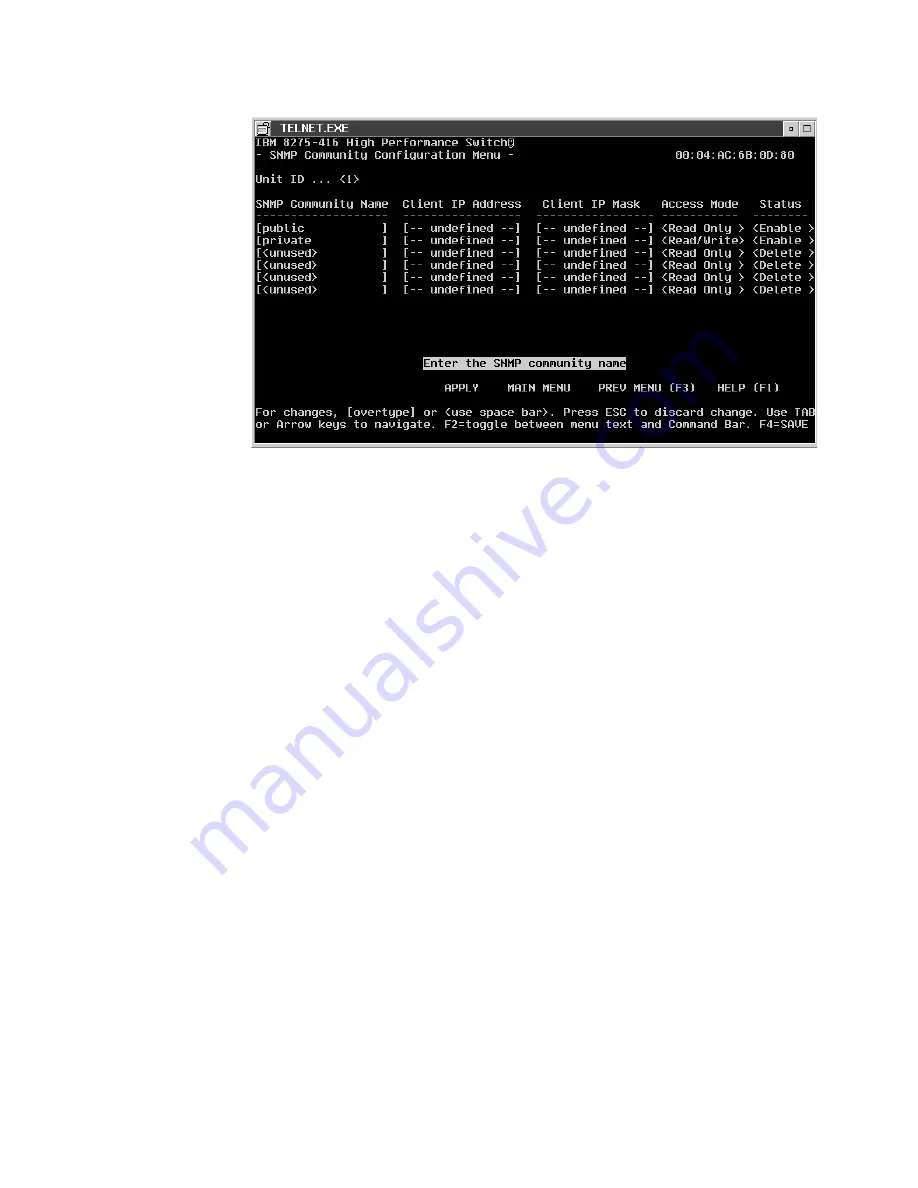
SNMP Community Name:

Name identifies each SNMP community and can be a string up to 32
characters. A

public

community means users have read only access. A

private

community is for users who have read/write access. Two

communities have default values. The default names are Public and
Private. You can replace these default community names with unique
identifiers for each community. The default value for the remaining four
community names are blank.

Access Mode:

This value can be read only or read/write. A community with a read only
access allows for 8275-416 information to be displayed. A community with a
read/write access allows for configuration changes to be made and for
information to be displayed.

Client IP Address

This attribute is an IP address (or portion thereof) from which this device
will accept SNMP packets with the associated community. The requesting
entity’s IP address is combined with the Client IP Mask before being
compared to the Client Ip Address. Note: If the Client IP Mask is set to
0.0.0.0, a Client IP Address of 0.0.0.0 matches all IP addresses.

Client IP Mask

This attribute is a mask to be combined with the requesting entity’s IP
address before comparison with Client IP Address. If the result matches
with Client IP Address then the address is an authenticated IP address . For
example, if the Client IP Address is 9.47.128.0 and the corresponding Client
Ip Mask is 255.255.255.0, a range of incoming IP addresses would match,
ie the incoming IP addresses could be a value in the following range:
9.47.128.0 - 9.47.128.255.

Status:

This attribute has the following values: Enable, Disable and Delete on the
Terminal and Web interface and Active, Inactive, and Delete via SNMP. A
status value of Enable/Active means that the community is active, allowing
SNMP managers associated using this community to manage the

Figure 20. SNMP Community Configuration

34

8275-416 User’s Guide

Summary of Contents for 8275

Page 1: ...8275 Model 416 High Performance Ethernet Workgroup Switch User s Guide GC30 4026 00 IBM...

Page 2: ......

Page 3: ...8275 Model 416 High Performance Ethernet Workgroup Switch User s Guide GC30 4026 00 IBM...

Page 4: ...iven below A form for readers comments appears at the back of this publication If the form has been removed address your comments to Department CGF Design Information Development IBM Corporation PO Bo...

Page 5: ...Configuring your 8275 416 17 Configuring IP information 17 Concepts About Making Configuration Changes 19 Making Configuration Changes 19 Processing Configuration Changes 19 Saving Configuration Chan...

Page 6: ...Management 52 System Utilities 53 Saving Applied Changes 53 Logging Out 53 Handling Files 54 Reset Utility 56 Resetting System 57 Resetting Configuration Data to Factory Default Values 57 Resetting Pa...

Page 7: ...75 Taiwanese Class A Warning Statement 76 Class 1 Laser Statement 76 Class 1 LED Statement 76 Trademarks 76 Appendix C Cable Pinout Diagrams 79 Straight Through 10BASE T 100BASE TX Cables 79 Straight...

Page 8: ...vi 8275 416 User s Guide...

Page 9: ...ration 35 22 Trap Flags Configuration 36 23 Trap Log 37 24 Trap Log Status 38 25 Telnet Configuration 39 26 Ping 40 27 ARP Cache 41 28 Device Configuration 42 29 Switch Configuration 43 30 Port Config...

Page 10: ...RJ 45 to IBM Data ConnectorCrossover 81 54 Pinout of the EIA 232 Port 81 55 EIA 232 Modem Cable for Terminal with 25 Pin Connector 82 56 EIA 232 Modem Cable for Terminal with 9 Pin Connector 82 viii...

Page 11: ...ments 4 2 Connectivity Methods and Available User Interfaces 11 3 MIBs Supported by the 8275 416 14 4 Troubleshooting Isolating Problems 64 5 Special Keys and Commands Used with the Terminal Interface...

Page 12: ...x 8275 416 User s Guide...

Page 13: ...the Terminal Interface describes the using functions of the terminal interface v Chapter 5 Using the Web Interface introduces the Web interface v Chapter 6 Troubleshooting and Obtaining Service gives...

Page 14: ...ubscribe to receive e mail notifications about code updates tips and FAQs for your 8275 416 Obtaining Service If you need assistance in troubleshooting or you need service for your 8275 416 call IBM a...

Page 15: ...Web interface SNMP v Backplane performance 10 Giga bits per second Ethernet switching v Desktop and segment switching infrastructure v Affordable migration to higher performance networks Network admin...

Page 16: ...that needs to be added to the table the frame is sent multicast Management and User Interfaces The network administrator has a choice of these easy to use management methods v A VT100 terminal interf...

Page 17: ...at all of its components are functioning correctly v Controls a seven segment LED that allows you to follow the boot sequence v Allows you to download software upgrades using any of the management met...

Page 18: ...s Max Cable Length 10BASE T Category 3 4 5 100 ohm STP UTP cable 100 m 328 ft 100BASE TX Category 5 100 ohm STP or UTP cable and connecting hardware 100 m 328 ft 100BASE FX 62 5 micron multimode fiber...

Page 19: ...DB 9 male connector that provides an EIA 232 serial interface sometimes referred to as the out of band management port Use a null modem serial cable when connecting to a workstation see Appendix C Ca...

Page 20: ...ate Explanation I Green ON There is power to the 8275 416 and the power supply is OK OFF There is no power is present or there is a power supply failure OK Green ON The 8275 416 is operational OFF The...

Page 21: ...Port LED Green ON Indicates a 100 Mbps port This LED being On only has meaning if the link is up OFF Indicates a 10 Mbps port This LED being Off only has meaning if the link is up Left Ethernet Port...

Page 22: ...rnet Feature Module LED Color State Explanation OK Green ON There is power to feature module OFF There is no power to feature module no power to the 8275 416 or the module has failed Fault Yellow ON T...

Page 23: ...x and receiving Rx traffic Physical Characteristics Physical characteristics for the 8275 416 are summarized in the following table Characteristic Specification Physical Dimensions Height 63 0 mm 2 48...

Page 24: ...ating Environment Operating Temperature 10 40 C 50 104 F Operating Humidity 8 80 Storage Temperature 1 60 C 33 8 140 F Storage Humidity 8 80 Shipment Temperature 40 C 60 C 104 F 140 F Shipment Humidit...

Page 25: ...faces that are available depending on your method of connectivity Table 2 Connectivity Methods and Available User Interfaces Connectivity Method Available User Interface Out of band Terminal interface...

Page 26: ...You may need to configure your terminal emulation application to enable use of these keys Remotely Attached Terminal To establish out of band connectivity using a remotely attached terminal make the...

Page 27: ...e is admin and the password is blanks no password i See Appendix D Interface Conventions for the Console on page 83 for a description of terminal interface key definitions You may need to configure yo...

Page 28: ...ort or a Telnet session For security a log in userid and password is required Multiple userids and associated passwords can be created Two levels of access privileges are supported read write and read...

Page 29: ...for the 8275 416 Web Based Management Interface The 8275 416 has a Web server that supports HTTP 1 1 and HTML 3 2 or later The Web browser must support HTTP 1 1 or HTML 3 2 or later The Web interface...

Page 30: ...16 8275 416 User s Guide...

Page 31: ...Your 8275 416 can be configured from remote locations using DHCP Dynamic Host Configuration Protocol or BootP BootP documented in RFC 951 and RFC 1542 is a bootstrap protocol used by a diskless workst...

Page 32: ...y configure the 8275 416 with the appropriate IP information To manually configure the IP information using the terminal interface select Network Connectivity Configuration Menu from the Management Me...

Page 33: ...dministered address must have bit 6 On B 1 and bit 7 Off B 0 MAC Address Type The burned in MAC address is the default MAC address type Concepts About Making Configuration Changes This section provide...

Page 34: ...sor to the appropriate field indicated by the direction of the arrow key pressed v Back Space Removes a character in front of the cursor v Delete Gives the same result as the Backspace v Enter The tex...

Page 35: ...Invalid data errors are reported one field at a time All configuration changes must be valid before any of the changes are processed v If the configuration change is processed successfully and UNSAVED...

Page 36: ...ing Configuration Changes On the Web pages field entries that can be modified are displayed in a box with a white background Depending on the field being modified you can modify the text by v Typing i...

Page 37: ...nges across a power cycle when using SNMP Making Configuration Changes You make configuration changes via SNMP by issuing SNMP Set commands to MIB objects that the 8275 416 supports as read write Proc...

Page 38: ...24 8275 416 User s Guide...

Page 39: ...in Panel The Login panel is the first panel displayed when initializing the terminal interface Figure 11 shows the Login panel you need an approved user name and password to log in User Name Can be up...

Page 40: ...5 416 User Account Management Allows you to define users and passwords and their level of access System Utilities Allows selection of the utilities available with the 8275 416 System Information The 8...

Page 41: ...d System Description Menu you can view information about your 8275 416 Figure 13 shows your system information options Inventory Information Figure 14 shows you inventory information available for you...

Page 42: ...System Description Figure 15 shows you a system description for your 8275 416 Figure 15 System Description 28 8275 416 User s Guide...

Page 43: ...Network Connectivity To configure the IP information using the terminal interface select Network Connectivity Configuration Menu from the Management Menu The Network Connectivity Configuration Menu ap...

Page 44: ...L bit indicates whether the address is universally administered B 0 or locally administered B 1 v Bit 7 of byte 0 called the I G bit indicates whether the destination address is an individual address...

Page 45: ...her a DHCP or BootP server The IP information in the BootP or DHCP response overlays any existing IP information in 8275 416 The new IP information is not retained across a reset until a SAVE is issue...

Page 46: ...he 8275 416 8275_416_Switch_1 ht ethernet ha 0004ac6b0980 ip 10 1 7 7 gw 10 1 1 1 sm 255 255 255 0 8275_416_Switch_2 ht ethernet ha 0004ac6b09C0 ip 10 1 7 8 gw 10 1 1 1 sm 255 255 255 0 Where ht hardw...

Page 47: ...based on your SNMP configuration SNMP configuration for the 8275 416 includes configuring the trap receiver and SNMP community parameters which are described in the following text Configuring the SNM...

Page 48: ...ty The requesting entity s IP address is combined with the Client IP Mask before being compared to the Client Ip Address Note If the Client IP Mask is set to 0 0 0 0 a Client IP Address of 0 0 0 0 mat...

Page 49: ...8275 416 or on the network Up to six simultaneous Trap Receivers are supported To configure Trap Receivers select SNMP Trap Receiver Configuration Menu on the Management Menu Figure 21 shows the param...

Page 50: ...ent the changes Warm start and cold start traps are always generated there are no associated trap conditions To configure trap conditions select Trap Menu from the Management Menu the select you condi...

Page 51: ...name a 16 byte character string of the trap condition which are v Warm Start v Cold Start v Authentication Failure v Link Up v Link Down v Multiple Users v New Spanning Tree Root v Spanning Tree Topol...

Page 52: ...ear the trap log on this panel see Figure 24 Configuring Telnet You can manage the 8275 416 remotely using a Telnet connection Chapter 2 Accessing the 8275 416 on page 11 describes setting up a Telnet...

Page 53: ...ou indicate that the value is to be applied or saved then no Telnet connections are allowed Any already established session remains active until the session is ended or an abnormal network error ends...

Page 54: ...sent every second Command Send is the only command To stop sending pings press F3 PREV MENU or select the Main Menu when sending continuous pings ARP Cache Select Management Menu from the Main Menu T...

Page 55: ...Figure 27 ARP Cache Chapter 4 Using the Terminal Interface 41...

Page 56: ...the 8275 416 Address Aging Timeout The 8275 416 allows you to set a time after which its address will timeout the address aging timeout This value can be set by selecting Device Configuration Menu fro...

Page 57: ...it to automatically determine the port type and speed See Chapter 3 Configuring your 8275 416 on page 17 for details about making and saving configuration changes You can configure the ports by select...

Page 58: ...ort is reset and the spanning tree state reported is Disabled until the Link is Up The 8275 416 ensures that the station is at the correct speed and duplex setting turns on the port LED that indicates...

Page 59: ...port1 ifIndex 9 is slot 0 port 9 ifIndex 17 is slot 1 port 1 ifIndex 25 is slot 2 port 1 if there are 24 ports 16 base ports 8 ports in slot 2 ifIndex 1 is slot 0 port1 ifIndex 9 is slot 0 port 9 ifIn...

Page 60: ...articipates in Spanning Tree Protocol STP STP allows you to configure redundant paths in the switch topology and have the 8275 416 automatically blocks redundant paths to prevent loops fault tolerant...

Page 61: ...ximum Age Time When the 8275 416 is root Maximum Age Time is the time in seconds after which the configuration message used by the Spanning Tree Algorithm is discarded The range is between 6 to 40 sec...

Page 62: ...higher the priority The 8275 416 with the lowest priority value becomes the root IEEE 802 1D The default is 128 Port Path Cost This output is automatically calculated The cost represents the shortest...

Page 63: ...n Menu Then from the Device Configuration Menu select 802 3x Flow Control Menu 802 3x Flow Control can be enabled or disabled the default is Disable See Figure 35 Figure 34 Broadcast Storm Recovery Fi...

Page 64: ...tics kept for your 8275 416 After making your selection the screens containing statistics will refresh every few seconds The following panels represent examples of the types of statistics that you can...

Page 65: ...Management Statistics See Figure 38 for a summary of port statistics Figure 37 Port Detailed Statistics Figure 38 Management Statistics Chapter 4 Using the Terminal Interface 51...

Page 66: ...sensitive A blank password indicates no password The default value is blank Confirm Password The confirm password can be up to eight alphanumeric characters The confirm password is not case sensitive...

Page 67: ...n the changes being retained across a reset v Pressing the F4 key v Selecting Save Applied Changes on the System Utilities Menu You can permanently save configuration changes by pressing the F4 key or...

Page 68: ...ieved from the 8275 416 as a binary file A binary configuration file can be sent to the 8275 416 This allows you to back up the configuration or to easily update the configuration of multiple 8275 416...

Page 69: ...275 416 to a remote server See Figure 43 The following parameters apply to uploading and downloading of files File Type The file types are For Download Figure 42 Downloading File to the 8275 416 Figur...

Page 70: ...ated The 8275 416 remembers the last file path used The default value is blank TFTP Server IP Address The IP address of the server where the file is located It is valid only when the Transfer Mode is...

Page 71: ...set None is the default Resetting Configuration Data to Factory Default Values 8275 416 allows you to reset the configuration to factory default values without powering off The factory defaults are no...

Page 72: ...efault Values 8275 416 allows you to reset user passwords to factory default values without powering off The factory defaults are not restored until the 8275 416 is reset The 8275 416 is automatically...

Page 73: ...he intended for use of this Debug function is for trained personel only You are prompted to indicate if want to continue Y yes or N no If you press Y the debug command line interface is used Debug uti...

Page 74: ...60 8275 416 User s Guide...

Page 75: ...consists of three frames Frame 1 across the top appears a banner graphic of the 8275 416 Frame 2 at the bottom left displays a hierarchical tree view The tree consists of a combination of folders sub...

Page 76: ...ire you to reset the system in order for them to take effect Apply Implements the changes you just made Some settings may require you to reset the system for them to take effect Refresh The Refresh bu...

Page 77: ...ch as workstations connected to an 8275 416 are unable to communicate with other devices in the network use the following steps to start the troubleshooting process 1 Locate the 8275 416 to which the...

Page 78: ...ure A Use this procedure if all LEDs are Off 1 Verify that the ac power outlet to which the 8275 416 power supply is connected is active If an uninterruptible power supply UPS is being used to provide...

Page 79: ...and connectivity c If ping is successfully received go to Step 5 d If the ping is not received go to Step 3 3 Restart the communications program on the failed connected device v If the communications...

Page 80: ...t v 1 800 772 2227 in the United States v 1 800 426 7378 1 800 IBM SERV in Canada v In other locations contact your place of purchase Refer to your IBM Warranty for information concerning service for...

Page 81: ...oe u electrische apparatuur op een veilige manier moet bekabelen en aansluiten Danger Avant de proc der l installation de ce produit lisez d abord les consignes de s curit dans la brochure ATTENTION C...

Page 82: ...SD21 0030 In dit boekje vindt u veilige procedures voor het aansluiten van elektrische appratuur VAARA Ennen kuin aloitat t m n tuotteen asennuksen lue julkaisussa Varoitus Turvaohjeet Lue t m ensin S...

Page 83: ...Safety Information Read This First SD21 0030 k nyvecsk ben le rt biztons gi inform ci kat Ez a k nyv le rja milyen biztons gi int zked seket kell megtenni az elektromos berendez s huzaloz sakor illetv...

Page 84: ...0 som beskriver sikkerhetsrutinene for kabling og tilkobling av elektrisk utstyr Perigo Antes de iniciar a instala o deste produto leia as informa es de seguran a Cuidado Informa es de Seguran a Leia...

Page 85: ...ento describe los procedimientos de seguridad para cablear y enchufar equipos el ctricos Varning livsfara Innan du b rjar installera den h r produkten b r du l sa s kerhetsinformationen i dokumentet V...

Page 86: ...72 8275 416 User s Guide...

Page 87: ...he copyright notice all warning statements and other required statements on each copy or partial copy v Transfer the original unaltered copy of the documentation when you transfer the related IBM prod...

Page 88: ...ean Norm EN Statement This product is in conformity with the protection requirements of EU Council Directive 89 336 EEC on the approximation of the laws of the Member States relating to electromagneti...

Page 89: ...g zu der industriellen St rquelle zu vergr ern Anmerkung Um die Einhaltung des EMVG sicherzustellen sind die Ger te wie in den IBM Handb chern angegeben zu installieren und zu betreiben Japanese Volun...

Page 90: ...serlaite Appareil Laser de Classe 1 To IEC 825 1 1993 Class 1 LED Statement Class 1 LED Product LED Klasse 1 LED Klass 1 Luokan 1 Ledlaite Appareil LED de Classe 1 To IEC 825 1 1993 Trademarks IBM is...

Page 91: ...Other company product and service names may be trademarks or service marks of other companies Appendix B Notices 77...

Page 92: ...78 8275 416 User s Guide...

Page 93: ...endix specifies Ethernet and null modem cable pinouts Straight Through 10BASE T 100BASE TX Cables Figure 48 Straight Through UTP Cable RJ 45 to RJ 45 T568A Figure 49 Straight Through UTP Cable RJ 45 t...

Page 94: ...les for STP Crossover 10BASE T 100BASE TX Cables Figure 50 Straight Through STP Cable RJ 45 to IBM Data Connector Figure 51 Crossover UTP Cable RJ 45 to RJ 45 T568A Figure 52 Crossover UTP Cable RJ 45...

Page 95: ...Crossover 10BASE T 100BASE TX Cables for STP EIA 232 Port Figure 53 Crossover STP Cable RJ 45 to IBM Data ConnectorCrossover Figure 54 Pinout of the EIA 232 Port Appendix C Cable Pinout Diagrams 81...

Page 96: ...Null Modem Cables Figure 55 EIA 232 Modem Cable for Terminal with 25 Pin Connector Figure 56 EIA 232 Modem Cable for Terminal with 9 Pin Connector 82 8275 416 User s Guide...

Page 97: ...ing the cursor keys No insert or overwrite modes can be performed in the field The text in the field is erased and replaced by the new text Pressing the Esc key before moving off the field restores th...

Page 98: ...sword are processed for login v On a non leaf menu option and press Enter the selected menu is displayed A non leaf menu is a panel that contains a list of menu names that can be selected v On the Uni...

Page 99: ...not accepted Uppercase Words in the Menu Identifies commands READ ONLY When in the upper right corner of the screen indicates that the current user has Read Only access UNSAVED DATA When in the upper...

Page 100: ...86 8275 416 User s Guide...

Page 101: ...ectivity 11 SNMP based management interface 14 terminal interface EIA 232 port 11 terminal interface Telnet 14 Add trap log operation 37 address aging 2 APPLY command 83 ARP Cache 40 ARP Cache Menu 40...

Page 102: ...s Menu 42 Spanning Tree Switch Configuration Status Menu 42 Switch Configuration Menu 42 DHCP Dynamic Host Configuration Protocol 17 down arrow 83 downloading code 56 downloading configuration file 56...

Page 103: ...SNMP Community Configuration Menu 29 SNMP Trap Receiver Configuration Menu 29 Telnet Menu 29 Trap Menu 29 view of 29 Maximum Age Time Spanning Tree Protocol default for 47 description of 47 menu comm...

Page 104: ...52 read only 34 Read Write 34 SNMP read write 3 security continued status 52 user accounts 3 SEND STOP command 83 Serial Port Configuration Menu Baud rate 30 description of 30 Time out 30 server confi...

Page 105: ...description of 53 Disable 53 Enable 53 range of values 53 stop bits 12 13 STP Spanning Tree Protocol 3 46 subet mask 19 subnet mask 13 System Information Menu description of 26 how to access 26 optio...

Page 106: ...anning Tree Topology Change 37 Warm Start 37 Traverse trap log operation 37 U Unit ID description of 33 range of values 33 UNSAVED DATA command 83 up arrow 83 uploading configuration file 56 uploading...

Page 107: ...his book is Very Satisfied Satisfied Neutral Dissatisfied Very Dissatisfied Accurate h h h h h Complete h h h h h Easy to find h h h h h Easy to understand h h h h h Well organized h h h h h Applicabl...

Page 108: ...IBM Corporation P O Box 12195 Research Triangle Park NC U S A 27709 9990 _ _ _ _ _ _ _ _ _ _ _ _ _ _ _ _ _ _ _ _ _ _ _ _ _ _ _ _ _ _ _ _ _ _ _ _ _ _ _ _ _ _ _ _ _ _ _ _ _ _ _ _ _ _ _ _ _ _ _ _ _ _ _ _...

Page 109: ......

Page 110: ...IBMR Printed in the United States of America on recycled paper containing 10 recovered post consumer fiber GC30 4026 00...

Reviews: