5.
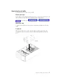
Use the thermal-grease syringe to place 9 uniformly spaced dots of 0.02 mL
each on the top of the microprocessor. The outermost dots must be within
approximately 5 mm of the edge of the microprocessor. This is to ensure
uniform distribution of the grease.
Note:
0.01 mL is one tick mark on the syringe. If the grease is properly applied,
approximately half (0.22 mL) of the grease will remain in the syringe.
6.
Install the heat sink onto the microprocessor as described in “Installing a
microprocessor and heat sink” on page 319.
Installing a hot-swap power supply
Use this information to install a hot-swap power supply.
Before you begin
The following notes describe the type of ac power supply that the server supports
and other information that you must consider when you install a power supply:
v
Make sure that the devices that you are installing are supported. For a list of
supported optional devices for the server, see http://www.ibm.com/systems/
info/x86servers/serverproven/compat/us.
v
Before you install an additional power supply or replace a power supply with
one of a different wattage, you may use the IBM Power Configurator utility to
determine current system power consumption. For more information and to
download the utility, go to http://www.ibm.com/systems/bladecenter/
resources/powerconfig.html.
v
The server comes with one hot-swap 12-volt output power supply that connects
to power supply bay 1. The input voltage is 110 V ac or 220 V ac auto-sensing.
v
Power supplies in the server must be with the same power rating or wattage to
ensure that the server will operate correctly.
v
Power supply 1 is the default/primary power supply. If power supply 1 fails,
you must replace the power supply with the same wattage immediately.
v
You can order an optional power supply for redundancy.
v
These power supplies are designed for parallel operation. In the event of a
power-supply failure, the redundant power supply continues to power the
system. The server supports a maximum of two power supplies.
Statement 5
CAUTION:
The power control button on the device and the power switch on the power
supply do not turn off the electrical current supplied to the device. The device
also might have more than one power cord. To remove all electrical current from
the device, ensure that all power cords are disconnected from the power source.
90
System x3500 M4 Type 7383: Installation and Service Guide
Summary of Contents for 7383
Page 1: ...System x3500 M4 Type 7383 Installation and Service Guide ...
Page 2: ......
Page 3: ...System x3500 M4 Type 7383 Installation and Service Guide ...
Page 8: ...vi System x3500 M4 Type 7383 Installation and Service Guide ...
Page 42: ...24 System x3500 M4 Type 7383 Installation and Service Guide ...
Page 200: ...182 System x3500 M4 Type 7383 Installation and Service Guide ...
Page 360: ...342 System x3500 M4 Type 7383 Installation and Service Guide ...
Page 416: ...398 System x3500 M4 Type 7383 Installation and Service Guide ...
Page 470: ...452 System x3500 M4 Type 7383 Installation and Service Guide ...
Page 479: ...Taiwan Class A compliance statement Notices 461 ...
Page 480: ...462 System x3500 M4 Type 7383 Installation and Service Guide ...
Page 487: ......
Page 488: ... Part Number 46W8192 Printed in USA 1P P N 46W8192 ...


