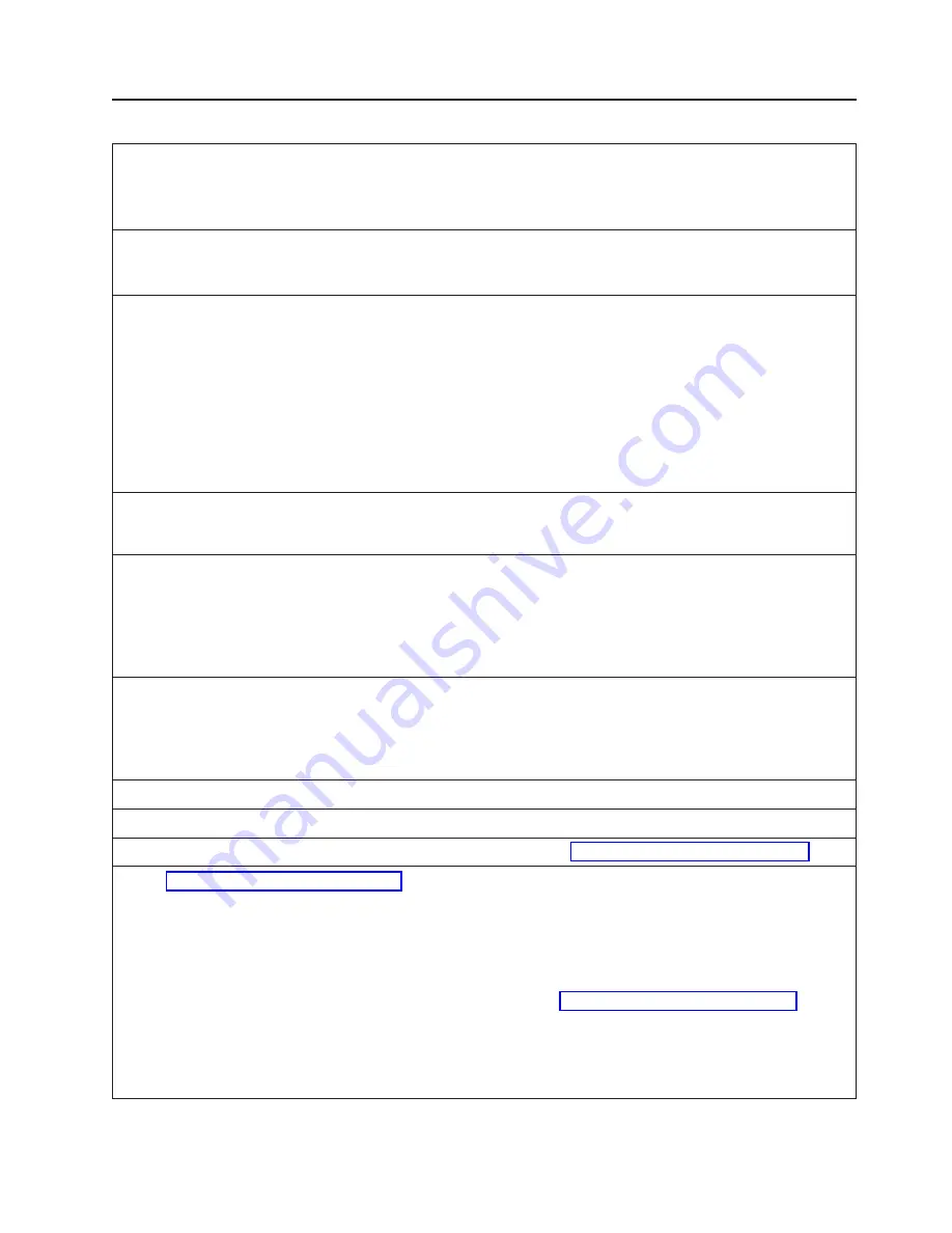
7015 POWERserver 970B and 980B
Dimensions
Height
1578 mm
62.0 in.
Width
650 mm
25.5 in.
Depth
921 mm
36.0 in.
Weight
Minimum
205kg
450 lbs.
Maximum
441kg
970 lbs.
Electrical
⁵
Maximum Entry
Maximum
Configuration
Configuration
Power source loading (max)
1.0
2.4
Voltage range (V ac)
200 to 240 or -48V dc
200 to 240 or -48V dc
Frequency (hertz)
50 or 60
50 or 60
Thermal output (max)
2165 Btu/hr
4100 Btu/hr
Power requirements (max)
634 watts
1200 watts
Power factor
⁴
0.5 to 0.7
0.5 to 0.7
Inrush current
⁶
125 amps
125 amps
Maximum altitude
2135 m (7000 ft.)
2135 m (7000 ft.)
Temperature Requirements
Operating
10 to 40°C
(50 to 104°F)
Non-Operating
10 to 52°C
(50 to 125°F)
Humidity (Noncondensing)
Operating
Non-Operating
Without tape drive
8 to 80%
8 to 80%
With tape drive
20 to 80%
20 to 80%
Wet Bulb Requirements
Without tape drive
27°C (80°F)
27°C (80°F)
With tape drive
23°C (73°F)
27°C (80°F)
Noise Emissions
1,2
Operating
Idle
L
WAd
6.4 bels
6.2 bels
L
pAm
N/A
N/A
<L
pA
>
m
49 dBA
47 dBA
Impulsive or prominent discrete tones
No
No
Clearances
³
Front
Back
Left
Right
Install/Air Flow
Maintenance of a proper service clearance should allow proper air flow
Service
(See service clearances for the “7015 System Rack R00” on page 41)
1. See “Noise Emission Notes” on page 336 for definitions of noise emissions positions.
2. Noise emissions data for the 7015 system unit is based on the following configuration: a processor drawer with
eight memory cards and eight I/O cards, a SCSI device drawer with four SCSI devices, the second eight I/O slots
with eight asynchronous cards, two SCSI disk drawers with four SCSI devices each, and a battery backup unit.
Noise emissions data for the SCSI disk drawer is therefore included in the data.
3. For multiple racks placed side by side, the left and right clearances apply only to the leftmost and rightmost rack.
For five to six racks placed side by side, the left and right clearances need to be increased to 1525 mm (60 in).
Having more than six racks side by side is not recommended. See “7015 System Rack R00” on page 41 for
additional clearance information.
4. Power factor is 0.7 to 0.9 without a battery backup unit.
5. The figures for power source loading, thermal output, and power requirement represent maximums. Work with
your sales or service representative to determine the typical figures for your configuration.
6. Inrush currents occur only at initial application of power, no inrush occurs during normal use.
Chapter 2. Physical Characteristics of Systems
37
Summary of Contents for 7012 397
Page 1: ...RS 6000 and Eserver pSeries Site and Hardware Planning Information SA38 0508 20...
Page 2: ......
Page 3: ...RS 6000 and Eserver pSeries Site and Hardware Planning Information SA38 0508 20...
Page 11: ...Appendix Notices 385 Index 387 Contents ix...
Page 12: ...x Site and Hardware Planning Information...
Page 16: ...xiv Site and Hardware Planning Information...
Page 18: ...xvi Site and Hardware Planning Information...
Page 26: ...8 Site and Hardware Planning Information...
Page 238: ...220 Site and Hardware Planning Information...
Page 246: ...228 Site and Hardware Planning Information...
Page 284: ...266 Site and Hardware Planning Information...
Page 296: ...278 Site and Hardware Planning Information...
Page 366: ...348 Site and Hardware Planning Information...
Page 372: ...Async Adapter Cable Planning Chart 354 Site and Hardware Planning Information...
Page 377: ...Standard I O Cable Planning Chart Chapter 12 Cable Planning 359...
Page 380: ...Cable Planning Chart Other Adapters 362 Site and Hardware Planning Information...
Page 384: ...366 Site and Hardware Planning Information...
Page 402: ...384 Site and Hardware Planning Information...
Page 404: ...386 Site and Hardware Planning Information...
Page 413: ......
Page 414: ...Printed in USA SA38 0508 20...
Page 415: ...Spine information RS 6000 and Eserver pSeries Site and Hardware Planning Information...


