


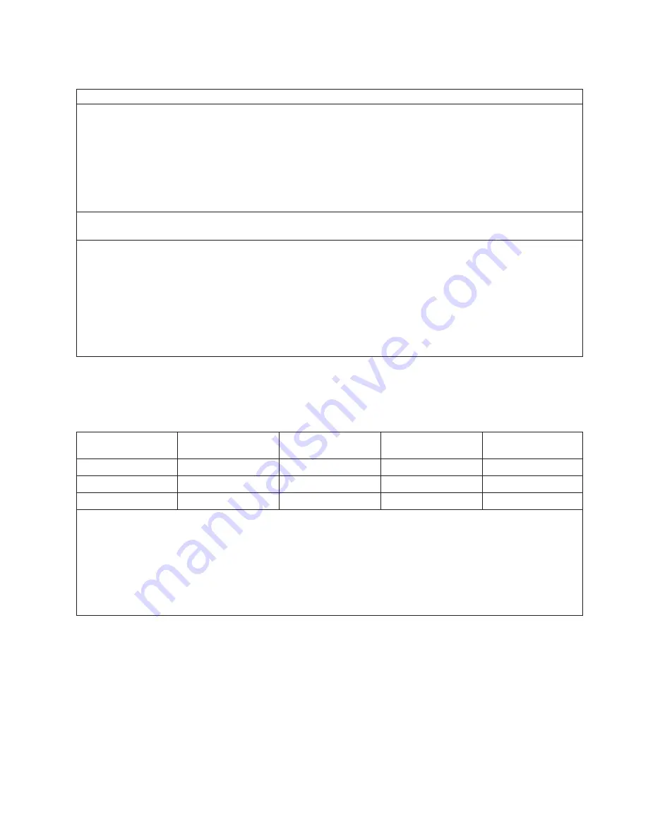
Environmental Specifications
Environmental Specification
Operating
Non-Operating
Storage
Shipping
Temperature
10 to 32°C
(50 to 90°F)
Max. of 24 ° C
(75.2 ° F) with
4mm tape or DVD
RAM in rear
positions of the
Media Subsystem
10 to 43°C
(50 to 109°F)
1 to 60°C
(34 to 140°F)
–40 to 60°C
(–40 to 140°F)
Relative Humidity
(Noncondensing)
8 to 80 %
8 to 80 %
5 to 80 %
5 to 100 %
Maximum Wet Bulb
23°C (73°F)
27°C (73°F)
29°C (84°F)
29°C (84°F)
Notes:
1. When an IBM-approved vapor bag and desiccant packets are used to protect the system, storage specifications
are valid for 6 months and shipping specifications are valid for 1 month. Otherwise, storage and shipping
specifications are valid for two weeks each.
2. The upper limit of the dry bulb temperature must be derated 1 degree C per 189 m (619 ft.) above 1295 m (4250
ft.). Maximum altitude for 1.1 GHz, 1.5 GHz, and 1.7 GHz modules is 3048 m (10,000 ft.) and for 1.3 GHz
modules is 2134 m (7000 ft).
Weight Distribution
The following table shows dimensions and weights used to calculate floor loading for the
Eserver
pSeries
690. All floor-loading calculations are intended for a raised-floor environment.
1 Frame with
Slimming Covers
2 Frames with
Slimming Covers
1 Frame with
Acoustical Covers
2 Frames with
Acoustical Covers
Weight
1170 kg (2580 lbs.)
1973 kg (4349 lbs.)
1184 kg (2610 lbs.)
2000 kg (4409 lbs.)
Width
750 mm (29.5 in.)
1539 mm (60.6 in.)
750 mm (29.5 in.)
1539 mm (60.6 in.)
Depth
1173 mm (46.2 in.)
1173 mm (46.2 in.)
1173 mm (46.2 in.)
1173 mm (46.2 in.)
Notes:
1. For 2 frame systems, widths of Frame A and Frame B. were added (the depth remains 1069 mm (42.1 in.), not
including frame extenders).
2. For 2 frame systems, weights are based on maximum configuration (less than addition of maximum weights for
each frame).
3. The values in the table may be used with the Floor Loading Calculation Program available on the IP Website.
4. All floor-loading calculations are intended for a raised-floor environment.
Chapter 2. Physical Characteristics of Systems
173
Summary of Contents for 7012 397
Page 1: ...RS 6000 and Eserver pSeries Site and Hardware Planning Information SA38 0508 20...
Page 2: ......
Page 3: ...RS 6000 and Eserver pSeries Site and Hardware Planning Information SA38 0508 20...
Page 11: ...Appendix Notices 385 Index 387 Contents ix...
Page 12: ...x Site and Hardware Planning Information...
Page 16: ...xiv Site and Hardware Planning Information...
Page 18: ...xvi Site and Hardware Planning Information...
Page 26: ...8 Site and Hardware Planning Information...
Page 238: ...220 Site and Hardware Planning Information...
Page 246: ...228 Site and Hardware Planning Information...
Page 284: ...266 Site and Hardware Planning Information...
Page 296: ...278 Site and Hardware Planning Information...
Page 366: ...348 Site and Hardware Planning Information...
Page 372: ...Async Adapter Cable Planning Chart 354 Site and Hardware Planning Information...
Page 377: ...Standard I O Cable Planning Chart Chapter 12 Cable Planning 359...
Page 380: ...Cable Planning Chart Other Adapters 362 Site and Hardware Planning Information...
Page 384: ...366 Site and Hardware Planning Information...
Page 402: ...384 Site and Hardware Planning Information...
Page 404: ...386 Site and Hardware Planning Information...
Page 413: ......
Page 414: ...Printed in USA SA38 0508 20...
Page 415: ...Spine information RS 6000 and Eserver pSeries Site and Hardware Planning Information...


