background image

8. Turn the storage-riser-card assembly to access the ServeRAID SAS controller.

9. Pull the controller from the connector on the storage-riser-card assembly.

10. Disconnect the battery cable from the battery cable interposer card.

11. Remove the storage-riser-card assembly and ServeRAID SAS controller from

the 3U chassis.

12. Slide and release the retention bracket that secures the fan assembly, and

remove the bracket from the chassis.

13. Lift up on both fan-assembly handles and remove the fans from the 3U

chassis.

14. Note the cable routing and connection locations; then, disconnect the cables

that connect the system-board tray to the 3U chassis.

15. Push on the back edge of the system-board tray from inside the 3U chassis

and slide the system-board tray forward.

16. Pull the system-board tray out of the 3U chassis and set it on a flat,

static-protective surface.

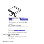
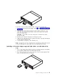
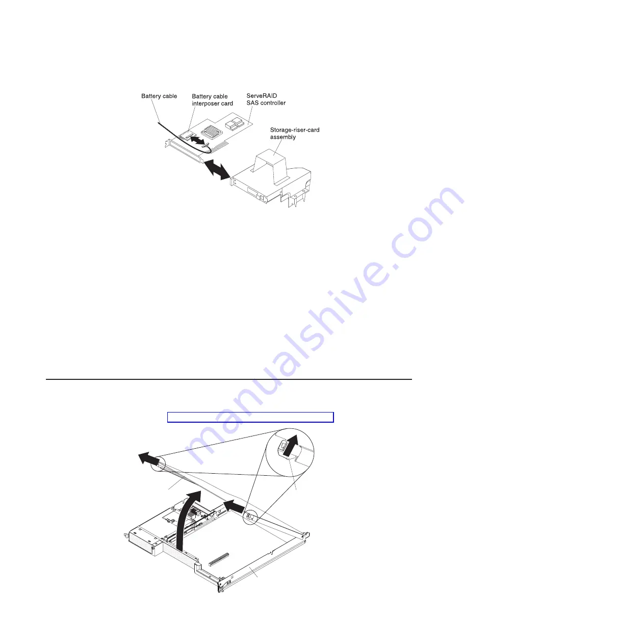
Removing the system-board tray cover

Note:

If an expansion enclosure is installed on the system-board tray, remove it

instead (see “Removing an expansion enclosure” on page 29).

Release
latch

System-board
tray cover

System-board
tray

28

System x iDataPlex dx360 M2: User's Guide

Summary of Contents for 6380

Page 1: ...System x iDataPlex dx360 M2 Types 6313 6380 6385 6386 7321 7323 7831 and 7834 User s Guide...

Page 2: ......

Page 3: ...System x iDataPlex dx360 M2 Types 6313 6380 6385 6386 7321 7323 7831 and 7834 User s Guide...

Page 4: ...s on page 71 the Environmental Notices and User s Guide and the Warranty and Support Information document on the IBM Documentation CD Fourth Edition June 2011 Copyright IBM Corporation 2011 US Governm...

Page 5: ...lling optional devices 23 Installation guidelines 23 System reliability guidelines 23 Handling static sensitive devices 24 Removing a 3U chassis from an iDataPlex rack 24 Removing a system board tray...

Page 6: ...m 63 Starting the LSI Logic Configuration Utility program 64 Formatting a SCSI hard disk drive 65 Creating a mirrored pair of SCSI hard disk drives 65 Configuring a ServeRAID controller 65 Firmware up...

Page 7: ...Index 77 Contents v...

Page 8: ...vi System x iDataPlex dx360 M2 User s Guide...

Page 9: ...tuotteen lue turvaohjeet kohdasta Safety Information Avant d installer ce produit lisez les consignes de s curit Vor der Installation dieses Produkts die Sicherheitshinweise lesen Prima di installare...

Page 10: ...e is evidence of fire water or structural damage v Disconnect the attached power cords telecommunications systems networks and modems before you open the device covers unless instructed otherwise in t...

Page 11: ...ces or regulations Statement 3 CAUTION When laser products such as CD ROMs DVD drives fiber optic devices or transmitters are installed note the following v Do not remove the covers Removing the cover...

Page 12: ...ton on the device and the power switch on the power supply do not turn off the electrical current supplied to the device The device also might have more than one power cord To remove all electrical cu...

Page 13: ...us voltage current and energy levels are present inside any component that has this label attached There are no serviceable parts inside these components If you suspect a problem with one of these par...

Page 14: ...xii System x iDataPlex dx360 M2 User s Guide...

Page 15: ...e Chapter 2 Components features and controls on page 11 for detailed information about the components in the customized server solutions The iDataPlex products come with a limited warranty For informa...

Page 16: ...ng documentation for the dx360 M2 system board tray 2U chassis and 3U chassis is provided in Portable Document Format PDF on the IBM Documentation CD v Environmental Notices and User s Guide This docu...

Page 17: ...Portable Document Format PDF and includes the IBM Documentation Browser to help you find information quickly Hardware and software requirements The IBM Documentation CD requires the following minimum...

Page 18: ...Alt F to use the xpdf search function within the document Click Help for detailed information about using the Documentation Browser Notices and statements in this document The caution and danger stat...

Page 19: ...le data rate 3 DDR3 800 1066 and 1333 MHz DIMMs only v Sizes 1 GB single rank 2 GB dual rank and 4 GB dual rank v Chipkill supported with selected DIMMs Integrated functions v Integrated management mo...

Page 20: ...virtual media key is installed remote presence function in a single chip The IMM provides advanced service processor control monitoring and alerting function If an environmental condition exceeds a th...

Page 21: ...rtual media key is required to enable the remote presence and blue screen capture features The remote presence feature provides the following functions Remotely viewing video with graphics resolutions...

Page 22: ...ernet controller v Integrated management module IMM v Power on self test POST with error logging of POST failures v Power management v Read only memory ROM checksums v Redundant Ethernet capabilities...

Page 23: ...g the life cycles of virtual resources For more information about IBM Systems Director see the documentation on the IBM Systems Director CD that comes with the server and the IBM xSeries Systems Manag...

Page 24: ...click UpdateXpress Note To install the UpdateXpress program you might have to use an external USB CD RW DVD drive such as the IBM and Lenovo part number 73P4515 or 73P4516 See Firmware updates on pag...

Page 25: ...nts features and controls This section describes the server components and configurations the server controls and light emitting diodes LEDs and how to turn the system board tray on and off Copyright...

Page 26: ...ponents The following illustration shows the major components in the dx360 M2 system board tray Note The illustrations in this document might differ slightly from your hardware 12 System x iDataPlex d...

Page 27: ...ard that are used for installing optional devices See Operator panel controls connectors LEDs and power on page 19 for information about the external connectors See the Problem Determination and Servi...

Page 28: ...shows the locations of the jumpers on the system board that relate to selected system functions See the Problem Determination and Service Guide for more information about using jumpers on the system b...

Page 29: ...chassis The 2U chassis contains a power supply and a fan assembly that provide operating power and cooling for all components in the chassis The 2U chassis can support two system board trays or one sy...

Page 30: ...ending on your server configuration it also provides support for the installation of up to twelve 3 5 inch hot swap SAS or SATA hard disk drives SAS and SATA hard disk drives cannot be used within the...

Page 31: ...v 3U storage server a 3U chassis that contains one dx360 M2 system board tray and integrated storage Note The illustrations in this document might differ slightly from your hardware 2U compute server...

Page 32: ...ed 3 5 inch simple swap SATA hard disk drives 2U storage server The 2U storage server consists of one dx360 M2 system board tray with the storage enclosure that is installed in a 2U chassis The storag...

Page 33: ...t emitting diodes LEDs and how to turn the system board tray on and off Front view The following illustration shows the controls connectors and LEDs on the front of the server The operator panel on th...

Page 34: ...n the system event log that is accessed in the Setup utility Locator LED This LED can be lit remotely by the system administrator to aid in visually locating the system board tray In an IPMI environme...

Page 35: ...Smart Launch Utility before you turn on the system board tray v You can press the power control button on the front of the system board tray see Operator panel controls connectors LEDs and power on p...

Page 36: ...PMI environment the system administrator can turn off the system board tray by using the IPMI chassis control command v If the operating system stops functioning you can press and hold the power contr...

Page 37: ...leg muscles v Back up all important data before you make changes to disk drives v Have a small flat blade screwdriver and a small Phillips screwdriver available v You do not have to turn off the syste...

Page 38: ...example wear an electrostatic discharge wrist strap if one is available v Handle the device carefully holding it by its edges or its frame v Do not touch solder joints pins or exposed circuitry v Do...

Page 39: ...s are installed then remove them see Removing a hard disk drive on page 30 Statement 4 18 kg 39 7 lb 32 kg 70 5 lb 55 kg 121 2 lb CAUTION Use safe practices when lifting 5 Remove the 2 screws and slid...

Page 40: ...devices see Turning off the system board tray on page 21 3 If external cables are connected to the front of the system board tray or expansion enclosure note where they are connected then remove them...

Page 41: ...then remove them 4 Remove the 3U chassis from the iDataPlex rack see Removing a 3U chassis from an iDataPlex rack on page 24 5 Press on the two release latches at the top rear edge of the top cover as...

Page 42: ...ndles and remove the fans from the 3U chassis 14 Note the cable routing and connection locations then disconnect the cables that connect the system board tray to the 3U chassis 15 Push on the back edg...

Page 43: ...re installed in a 2U chassis covers must be installed on both of them Removing an expansion enclosure Release latch Expansion enclosure System board tray To remove an expansion enclosure complete the...

Page 44: ...move a hot swap drive To remove a hot swap hard disk drive complete the following steps 1 Read the safety information that begins on page vii and Installation guidelines on page 23 2 Rotate the drive...

Page 45: ...other then pull the drive out of the drive bay Note A hard disk drive or filler panel must always be installed in each drive bay when the server is turned on In each drive bay that contains a simple s...

Page 46: ...om a 2U chassis To remove a 2 5 inch simple swap hard disk drive or solid state drive complete the following steps 1 Read the safety information that begins on page vii and Installation guidelines on...

Page 47: ...s One slot riser card PCIe x16 x16 adapters Two slot riser card PCIe x16 x8 adapters Important The x8 designation identifies an x16 connector that supports x8 adapters and x16 adapters that can downsh...

Page 48: ...installed in the riser card remove it 8 Touch the static protective package that contains the adapter that you are installing to any unpainted metal surface on the chassis or rack then remove the adap...

Page 49: ...page 25 4 Remove the expansion enclosure see Removing an expansion enclosure on page 29 and set it upside down on a flat static protective surface Note If an adapter is already installed in the riser...

Page 50: ...lign the tabs on the PCIe adapter bay cover with the holes on the expansion enclosure then slide the PCIe adapter bay cover toward the rear of the expansion enclosure until it stops 14 Install the PCI...

Page 51: ...rive bay then carefully slide the drive into the bay until the drive stops 5 Rotate the drive tray handle to the closed position Note If you install or remove a hard disk drive see the documentation t...

Page 52: ...h other then carefully slide the drive into the bay until it stops and release the loops Note Do not release the loops on the drive until it is completely seated 7 Install the filler panel in the simp...

Page 53: ...drive with the guide rails in the drive bay then carefully slide the drive into the bay until the drive stops 5 Rotate the drive tray handle to the closed position Note If you install or remove a hard...

Page 54: ...RAID adapter and you install or remove a hard disk drive see the documentation that comes with your RAID adapter for information about reconfiguring the disk arrays Installing a memory module The foll...

Page 55: ...ach microprocessor However to improve system performance install a minimum of three DIMMs for each installed microprocessor v The maximum operating speed of the system board tray is determined by the...

Page 56: ...DIMMs to the backup pair of DIMMs You must enable memory mirroring through the Setup utility See Using the Setup utility on page 54 When you use the memory mirroring mode you must consider the followi...

Page 57: ...the system board tray the system displays a message that indicates that the memory configuration has changed To install a DIMM complete the following steps 1 Read the safety information that begins o...

Page 58: ...nap into the locked position when the DIMM is firmly seated in the connector Attention If there is a gap between the DIMM and the retaining clips the DIMM has not been correctly installed Open the ret...

Page 59: ...2 Install the system board tray in the chassis see Reinstalling a system board tray in a 2U chassis on page 47 or Reinstalling a system board tray in a 3U chassis on page 48 3 Connect the cables For...

Page 60: ...ection Expansion enclosure System board tray To reinstall an expansion enclosure complete the following steps 1 Orient the expansion enclosure above the system board tray 2 Lower the expansion enclosu...

Page 61: ...s and the release handles click into place 3 Reconnect the cables on the front of the system board tray 4 Turn on the system board tray see Turning on the system board tray on page 21 5 Make sure that...

Page 62: ...y into the 3U chassis until it stops 2 Reconnect the cables that connect the system board tray and optional adapter to the 3U chassis 3 Turn the fan assembly so that the connector aligns correctly wit...

Page 63: ...the signal cables to the ServeRAID SAS controller 11 Align the top cover assembly with the rear of the 3U chassis then slide it forward until it clicks into place 12 Reinstall the 3U chassis in the iD...

Page 64: ...lign the 3U chassis with the rails on the iDataPlex rack then slide the 3U chassis into the rack until it is fully seated 2 Install the M6 screws that secure the chassis to the rack 3 Install the hard...

Page 65: ...evice If the server has an optional RAID adapter and you have installed or removed a hard disk drive see the documentation that comes with the RAID adapter for information about reconfiguring the disk...

Page 66: ...52 System x iDataPlex dx360 M2 User s Guide...

Page 67: ...remotely manage a network For information about using the IMM see Using the integrated management module on page 59 v Remote presence capability and blue screen capture The remote presence and blue s...

Page 68: ...flash drive that comes with the iDataPlex rack when you run the DSA Preboot diagnostic programs on an iDataPlex server To download the most current USB or ISO image of the DSA Preboot diagnostic progr...

Page 69: ...tions in the Setup utility the changes are reflected in the system summary you cannot change settings directly in the system summary Product Data Select this choice to view the system board identifier...

Page 70: ...Reset IMM to Defaults Select this choice to view or reset IMM to the default settings Adapters and UEFI Drivers Select this choice to view information about the adapters and UEFI drivers in the server...

Page 71: ...ssages in the system event log Clear System Event Log Select this choice to clear the system event log v User Security Select this choice to set change or clear passwords See Passwords on page 58 for...

Page 72: ...ministrator can give the user authority to set change and delete the power on password A user who types the power on password has access to only the limited Setup utility menu the user can set change...

Page 73: ...r the location of the JP2 jumper Use the backup copy of the UEFI firmware until the primary copy is restored After the primary copy is restored turn off the server then move the JP2 jumper back to the...

Page 74: ...t sequence manipulation The IMM also provides the following remote server management capabilities through the OSA SMBridge management utility program v Command line interface IPMI Shell The command li...

Page 75: ...ist in determining the cause of the hang condition Enabling the remote presence feature To enable the remote presence feature complete the following steps 1 Install the virtual media key into the dedi...

Page 76: ...ut value in minutes in the field that is provided The IMM will log you off of the Web interface if your browser is inactive for the number of minutes that you entered for the timeout value 4 Click Con...

Page 77: ...er for the Ethernet controller you might have to use an external USB CD RW DVD drive such as the IBM and Lenovo part number 73P4515 or 73P4516 See Firmware updates on page 66 for additional instructio...

Page 78: ...vides additional RAID levels v When you create a RAID level 1 mirrored pair all drives must be on the same channel v Hard disk drive capacities affect how you create arrays The drives in an array can...

Page 79: ...eys or the End key 4 To start the low level formatting operation select Format and press Enter Creating a mirrored pair of SCSI hard disk drives To create a mirrored pair of SCSI hard disk drives comp...

Page 80: ...riodically updated and is available for download from the Web To check for the latest level of firmware such as BIOS code vital product data VPD code device drivers and service processor firmware comp...

Page 81: ...D or DVD containing the firmware update into the CD or DVD drive 10 Select Save Changes and Exit and follow the prompts Updating IBM Systems Director If you plan to use IBM Systems Director to manage...

Page 82: ...o http www ibm com eserver support fixes fixcentral 3 From the Product family list select IBM Systems Director 4 From the Product list select IBM Systems Director 5 From the Installed version list sel...

Page 83: ...by following the troubleshooting procedures that IBM provides in the online help or in the documentation that is provided with your IBM product The documentation that comes with IBM systems also desc...

Page 84: ...Line in your country or region see http www ibm com services sl products For more information about Support Line and other IBM services see http www ibm com services or see http www ibm com planetwide...

Page 85: ...s or implied warranties in certain transactions therefore this statement may not apply to you This information could include technical inaccuracies or typographical errors Changes are periodically mad...

Page 86: ...formance CD or DVD drive speed is the variable read rate Actual speeds vary and are often less than the possible maximum When referring to processor storage real and virtual storage or channel volume...

Page 87: ...n the equipment is operated in a commercial environment This equipment generates uses and can radiate radio frequency energy and if not installed and used in accordance with the instruction manual may...

Page 88: ...itting of non IBM option cards This product has been tested and found to comply with the limits for Class A Information Technology Equipment according to CISPR 22 European Standard EN 55022 The limits...

Page 89: ...Japanese Voluntary Control Council for Interference VCCI statement Korean Class A warning statement Appendix B Notices 75...

Page 90: ...76 System x iDataPlex dx360 M2 User s Guide...

Page 91: ...ed pair of hard disk drives 65 D danger statements 4 device drivers 9 DIMMs connector locations 41 installing 40 memory mirroring 41 order of installation 41 documentation CD 3 drive connectors 13 spe...

Page 92: ...ications 5 microprocessor connector location 13 specifications 5 N notes 4 notes important 72 notices 71 electronic emission 73 FCC Class A 73 notices and statements 4 O obtaining the IP address for w...

Page 93: ...alling 45 removing 28 system error LED 20 systems management 7 8 T telephone numbers 70 trademarks 71 turning off the system board tray 21 turning on the system board tray 21 T V gloss statement 73 U...

Page 94: ...80 System x iDataPlex dx360 M2 User s Guide...

Page 95: ......

Page 96: ...Part Number 90Y5680 Printed in USA 1P P N 90Y5680...

Reviews: