background image

Specifications

The specifications of the UPS models and the extended battery modules are shown
in the following tables.

Note:

All dimensions include the front bezel.

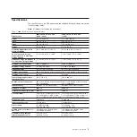
Table 1. 6000 VA LCD 4U rack UPS specifications

Specification

6000 VA LCD 4U rack UPS
(200 V / 208 V)

6000 VA LCD 4U rack UPS
(230 V)

Height

171.5 mm (6.8 in.)

171.5 mm (6.8 in.)

Width

483 mm (19 in.)

483 mm (19 in.)

Depth

735 mm (28.9 in.)

735 mm (28.9 in.)

Weight

72 kg (159 lb)

72 kg (159 lb)

Operating temperature at 0 to
maximum altitude

0°C to 40°C (32°F to 104°F)

0°C to 40°C (32°F to 104°F)

24 hour transport storage
temperature at 0 to maximum
storage altitude

-15°C to 60°C (5°F to 140°F)

-15°C to 60°C (5°F to 140°F)

Extended storage temperature at
0 to maximum storage altitude

-15°C to 45°C (5°F to 113°F)

-15°C to 45°C (5°F to 113°F)

Maximum operating altitude

3048 m (10,000 ft)

3048 m (10,000 ft)

Maximum storage altitude

15,240 m (50,000 ft)

15,240 m (50,000 ft)

Relative humidity

0 to 95% noncondensing

0 to 95% noncondensing

Nominal input voltage

208 V (auto sensing at first power-up) 230 V (auto sensing at first power-up)

Maximum input current

30 amps

32 amps

Input voltage range for main
operations (V ac)

155 to 255 V ac

160 to 286 V ac

Nominal output voltage (V ac)

208 V (auto sensing at first power-up;
user configurable)

230 V (auto sensing at first power-up;
user configurable)

Input frequency

50/60 Hz ± 3 Hz (auto sensing)

50/60 Hz ± 3 Hz (auto sensing)

Rated power output

6000 VA

6000 VA

Output power capacity in watts

5600 W

5600 W

Circuit breakers

Three two-pole output breakers: two
for Load Segment 1 rated at 20 A,
one for Load Segment 2 rated at 30 A

Three single-pole output breakers: two
for Load Segment 1 rated at 20 A, one
for Load Segment 2 rated at 15 A

Fixed power cord

Hard-wired

Hard-wired

Input connection type

Terminal block

Terminal block

Power outlets

Two NEMA L6-30R
Four IEC 320 - C19

Six IEC 320 - C13
Four IEC 320 - C19

Audible noise at 1 meter for >
80% load

<55 dBA normal / Bypass mode
<55 dBA Battery mode

<55 dBA normal / Bypass mode
<55 dBA Battery mode

Runtime (for fully charged
internal batteries at 25°C)

Full load: 5 min
Half load: 14 min

Full load: 5 min
Half load: 14 min

Chapter 1. Introduction

3

Summary of Contents for 6000 VA LCD 4U

Page 1: ...6000 VA LCD 4U Rack UPS 6000 VA UPS 3U Extended Battery Module Installation and Maintenance Guide...

Page 2: ......

Page 3: ...6000 VA LCD 4U Rack UPS 6000 VA UPS 3U Extended Battery Module Installation and Maintenance Guide...

Page 4: ...formation and Environmental Notices and User Guide documents on the IBM Documentation CD and the Warranty Information document that comes with the product Second Edition June 2012 Copyright IBM Corpor...

Page 5: ...Ennen kuin asennat t m n tuotteen lue turvaohjeet kohdasta Safety Information Avant d installer ce produit lisez les consignes de s curit Vor der Installation dieses Produkts die Sicherheitshinweise...

Page 6: ...atement are in the Safety Information document under Statement 1 Be sure to read all caution and danger statements in this document before you perform the procedures Read any additional safety informa...

Page 7: ...v Connect any equipment that will be attached to this product to properly wired outlets v When possible use one hand only to connect or disconnect signal cables v Never turn on any equipment when ther...

Page 8: ...ess for the collection of this battery For information call 1 800 426 4333 Have the IBM part number for the battery unit available when you call C004 CAUTION or 32 kg 70 5 lb or 32 55 kg 70 5 121 2 lb...

Page 9: ...es are not to be used as shelves or work spaces Do not place objects on top of rack mounted devices v Each rack cabinet might have more than one power cord Be sure to disconnect all power cords in the...

Page 10: ...er at a time v For fixed drawers This drawer is a fixed drawer and must not be moved for servicing unless specified by the manufacturer Attempting to move the drawer partially or completely out of the...

Page 11: ...e UPS input for licensed electrician only 14 UPS initial startup 17 Chapter 3 Operating the uninterruptible power supply 19 Control panel 19 Operating modes 20 Normal mode 20 Battery mode 20 Bypass mo...

Page 12: ...o collect alarm history 48 Typical alarms and conditions 51 Silencing the alarm 54 Low battery alarm or error message 55 Recharging internal batteries 55 Appendix A Getting help and technical assistan...

Page 13: ...stries Association JEITA statement 66 Korea Communications Commission KCC statement 66 Russia Electromagnetic Interference EMI Class A statement 67 People s Republic of China Class A electronic emissi...

Page 14: ...xii 6000 VA UPS and 6000 VA EBM Installation and Maintenance Guide...

Page 15: ...g and configuring the UPS v Solving problems If firmware and documentation updates are available you can download them from the IBM web site The UPS might have features that are not described in the d...

Page 16: ...t the CD into the CD drive and click Start Run In the Open field type e win32 bat where e is the drive letter of the CD drive and click OK If you are using Red Hat Linux insert the CD into the CD driv...

Page 17: ...put voltage 208 V auto sensing at first power up 230 V auto sensing at first power up Maximum input current 30 amps 32 amps Input voltage range for main operations V ac 155 to 255 V ac 160 to 286 V ac...

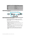
Page 18: ...cument v Note These notices provide important tips guidance or advice v Important These notices provide information or advice that might help you avoid inconvenient or problem situations v Attention T...

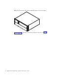
Page 19: ...the UPS v One number 2 Phillips screwdriver for use with the rack mount kit and terminal block cover v One flat blade screwdriver for wiring the terminal block Inventory checklist The UPS comes with...

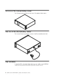
Page 20: ...in this document might differ slightly from your hardware For more information about the control panel on the front of the UPS see Control panel on page 19 6 6000 VA UPS and 6000 VA EBM Installation...

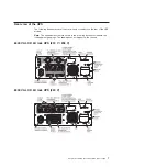
Page 21: ...ear of the UPS models Note The shaded areas that are shown in the following illustrations indicate the load segment groupings The shading does not appear on the chassis 6000 VA LCD 4U rack UPS 200 V 2...

Page 22: ...extended battery module The following illustration shows the rear view of the 3U extended battery module Rack installation To install the UPS or extended battery module in a rack cabinet see the IBM R...

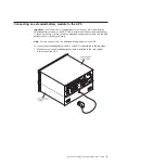
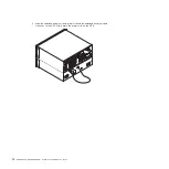
Page 23: ...e any safety concern Insert the extended battery module cable into the UPS battery connector quickly and firmly Note You can connect only one extended battery module to the UPS To connect an extended...

Page 24: ...ign the extended battery module power cord with the extended battery module connector on the UPS Firmly press the power cord into the UPS 10 6000 VA UPS and 6000 VA EBM Installation and Maintenance Gu...

Page 25: ...nables you to turn off power at the UPS output receptacles from a customer supplied switch in a remote location For example you can use this feature to shut down the load and the UPS by thermal relay...

Page 26: ...off function before you apply your critical load To connect a remote emergency power off switch complete the following steps 1 Turn off the UPS disconnect all external cables and make sure that the U...

Page 27: ...install it Remote emergency power off connector Openings 4 Connect the switch or circuit to the remote emergency power off connector on the rear of the UPS using insulated size 18 20 AWG 0 75 mm2 0 5...

Page 28: ...ide short circuit and overcurrent protection For Europe The breaker meets the IEC EN 60934 standard and has a contact air gap of at least 3 mm v A two pole disconnection device between the UPS output...

Page 29: ...a 20 25 5 mm 0 75 1 in Intermediate Metal Conduit IMC 4 Pull the input wire through the conduit leaving approximately 0 5 m 2 ft of exposed wire Attach a flexible metal fitting to the end of the cond...

Page 30: ...ning torque Input 1 Input ground 5 26 16 mm2 10 6 AWG 2 49 Nm 22 inch pounds 2 L2 Neutral In 3 L1 In 1 Use the following minimum wire size v 5 26 mm 10 AWG for equipment grounding wire 75 C copper wir...

Page 31: ...ency power off switch make sure that the function is working correctly by performing the following tests v Activate the external remote emergency power off switch Make sure that the status changes on...

Page 32: ...18 6000 VA UPS and 6000 VA EBM Installation and Maintenance Guide...

Page 33: ...lay LCD with dual color backlight Standard backlight is used to light up the display with white text and a blue background The display flashes if any alarms are active There are three control buttons...

Page 34: ...ing normally it might attempt to save data and follow an orderly shutdown sequence However some unrecoverable failures and overload conditions cause the UPS to transfer to Fault mode without saving da...

Page 35: ...devices for shutdown 2 Press and hold the on off button until the long beep ceases approximately 3 seconds The UPS switches to Standby mode if utility power is available and removes power from the con...

Page 36: ...ry disconnected Batteries are unavailable because they are disconnected Alarm history The alarm history holds up to 50 events You can scroll through the event screens beginning with the most recent ev...

Page 37: ...t on off controls made by the Automatic Start Delay and Automatic On Battery Shutdown settings See Configuring load segments on page 27 Restore factory settings Restore Factory Settings yes no Availab...

Page 38: ...t on the language selection 2 Time is a 24 hour clock Control commands from serial port Enabled Disabled If Enabled control commands are accepted through the serial port USB ports or option card If Di...

Page 39: ...errule the Bypass Voltage High Limit setting 10 of nominal Qualify bypass Always Never Bypass Disabled If Always Bypass operation is allowed when v Bypass voltages the value set for Bypass Voltage Low...

Page 40: ...ain menu press the down button to scroll to the Control menu and press the OK button 2 Press the down button to scroll to Go to Bypass and press the OK button The text on the screen changes to Manual...

Page 41: ...d segments are sets of receptacles that can be controlled through the LCD by the network management card or by power management software providing an orderly shutdown and startup of the connected devi...

Page 42: ...m 6 Repeat step 3 to step 5 to set the other load segment if applicable Notes 1 Load segment on off commands that are issued through the Control menu override the user settings for load segments 2 A s...

Page 43: ...shutdown warning prematurely Conversely if the UPS is configured for the extended battery module but the extended battery module is not connected to the UPS the UPS reports more battery time remainin...

Page 44: ...l mode with no active alarms v The load is greater than 10 v The bypass voltage is usable Configuring automatic battery tests To configure the automatic battery tests complete the following steps 1 Fr...

Page 45: ...IBM UPS Manager CD that comes with the UPS into the CD or DVD drive If the Software Wizard install menu does not automatically open see the CD_ReadMe txt file and follow the steps to manually open th...

Page 46: ...2 connector are identified in the following illustration The pin functions are described in Table 10 Table 10 RS 232 connector pin assignments Pin Signal name Function Direction from the UPS 1 Unused...

Page 47: ...ng configuring and using the network management card see the IBM Network Management Card User s Guide on the IBM Documentation CD that comes with the UPS For details about disabling control commands f...

Page 48: ...ring only during the 2 day charging cycle This means that 90 of the time there is no additional corrosion During this 30 day cycle the battery voltage drops by less than 2 which has no effect on the b...

Page 49: ...ause of transportation and logistics Table 11 UPS CRU listing Description MTM or part number CRU part number Tier 1 UPS chassis 6000 VA 200 V 208 V 5395 6AX 81Y2313 UPS chassis 6000 VA 230 V 5395 6KX...

Page 50: ...without load The charging can occur with the UPS connected to a power outlet it automatically goes to Standby mode and not turned on Replacing the battery modules for qualified personnel only CAUTION...

Page 51: ...arm is on continuously you might have to replace the battery module Contact your technical support representative to order new batteries Important Do not disconnect the batteries while the UPS is in B...

Page 52: ...Press the two side latchs toward each other to release the bezel and pull the bezel away Repeat for the second bezel 2 Disconnect both internal battery connectors unclip the connectors from the studs...

Page 53: ...umbscrew on the battery retaining bracket 1 b Slide the battery retaining bracket to the left 2 c Rotate the battery retaining bracket out 3 d Slide the battery retaining bracket to the right and remo...

Page 54: ...equires two people to lift it 5 With two people pull each battery module fully out of the bay and recycle or discard them as instructed by local regulations 6 With two people carefully slide one new b...

Page 55: ...y c Slide the battery retaining bracket to the right 3 d Tighten the thumbscrew on the battery retaining bracket 4 8 Connect each internal battery connector 5 and attach the connectors to the battery...

Page 56: ...the UPS front bezel press the two side latches toward each other align the bezel with the UPS and snap it into place Repeat for the second bezel 42 6000 VA UPS and 6000 VA EBM Installation and Mainte...

Page 57: ...the Control menu and press the OK button 3 Press the down button to scroll to Battery Test 4 Press the OK button to view the Battery Test status Note If the battery test is already scheduled or runnin...

Page 58: ...indicated for one battery only To measure the voltage value you must disconnect any batteries that are connected to each other The battery voltage must be measured at the battery connectors as shown...

Page 59: ...battery charge remains at 99 even after you replace the batteries The charge value is displayed as 99 on the UPS LCD panel and the IBM UPS Manager software This does not indicate a hardware failure a...

Page 60: ...46 6000 VA UPS and 6000 VA EBM Installation and Maintenance Guide...

Page 61: ...ation from two main menus on the display v UPS status Access to all active alarms and battery data v Alarm history Access to the most recent 50 events which might include active and closed alarms You...

Page 62: ...ory Through a serial connection you can access the last 50 events notices and alarms that are recorded in the UPS alarm history The events are arranged from latest to oldest Note Make sure that there...

Page 63: ...en click Disconnect 5 Click File Properties Set the computer ASCII settings as shown in the following illustration 6 Type GH and press Enter The UPS replies with a list of events that includes the eve...

Page 64: ...vent 181 03 09 2010 07 29 39 UPS Control Power ON 7 Select the text that you want right click the mouse and click Copy The list of events is copied to your computer clipboard 8 Press Ctrl V to paste t...

Page 65: ...ation port or an optional network management card does not operate The communication cable is not compatible Make sure that the correct communication cable is connected to the port or network manageme...

Page 66: ...to shutdown then apply utility power for 48 hours to recharge the batteries Note The UPS can be charged with or without load The charging can occur with the UPS connected to a power outlet it automat...

Page 67: ...drops below 5 of the set point Battery DC Over Voltage Alarm 68 Fast Beeping Alarm The battery voltage levels have exceeded the maximum allowable limits The UPS turns off the charger until the next p...

Page 68: ...ge Notice 3 Slow Intermittent Alarm The measured voltage on Bypass has exceeded the upper voltage limit specification for bypass operation Check the bypass utility Check that the Bypass settings are c...

Page 69: ...battery connector disconnected to avoid premature discharge of the battery The battery is expected to last at least six months from the manufacture date before requiring a recharge of the battery If...

Page 70: ...56 6000 VA UPS and 6000 VA EBM Installation and Maintenance Guide...

Page 71: ...roven compat us to make sure that the hardware and software is supported by your IBM product v Go to http www ibm com supportportal to check for information to help you solve the problem v Gather the...

Page 72: ...er information is http www ibm com systems bladecenter The address for IBM IntelliStation information is http www ibm com systems intellistation How to send Dynamic System Analysis data to IBM Use the...

Page 73: ...tp www ibm com partnerworld and click Find Business Partners on the right side of the page For IBM support telephone numbers see http www ibm com planetwide In the U S and Canada call 1 800 IBM SERV 1...

Page 74: ...60 6000 VA UPS and 6000 VA EBM Installation and Maintenance Guide...

Page 75: ...FOR A PARTICULAR PURPOSE Some states do not allow disclaimer of express or implied warranties in certain transactions therefore this statement may not apply to you This information could include techn...

Page 76: ...nel volume KB stands for 1024 bytes MB stands for 1 048 576 bytes and GB stands for 1 073 741 824 bytes When referring to hard disk drive capacity or communications volume MB stands for 1 000 000 byte...

Page 77: ...Limits Particulate v The room air must be continuously filtered with 40 atmospheric dust spot efficiency MERV 9 according to ASHRAE Standard 52 21 v Air that enters a data center must be filtered to...

Page 78: ...rence to radio communications Operation of this equipment in a residential area is likely to cause harmful interference in which case the user will be required to correct the interference at his own e...

Page 79: ...es Produkt entspricht den Schutzanforderungen der EU Richtlinie 2004 108 EG zur Angleichung der Rechtsvorschriften ber die elektromagnetische Vertr glichkeit in den EU Mitgliedsstaaten und h lt die Gr...

Page 80: ...en Germany Telephone 49 7032 15 2941 Email lugi de ibm com Generelle Informationen Das Ger t erf llt die Schutzanforderungen nach EN 55024 und EN 55022 Klasse A VCCI Class A statement This is a Class...

Page 81: ...e A Sellers and users need to pay attention to it This is for any areas other than home Russia Electromagnetic Interference EMI Class A statement People s Republic of China Class A electronic emission...

Page 82: ...68 6000 VA UPS and 6000 VA EBM Installation and Maintenance Guide...

Page 83: ...hrough LCD 27 CRU listing 35 D danger statements 4 diagnostic data 58 display function alarm history 22 configuration 24 control screens 23 meters 22 model information 23 display function continued sy...

Page 84: ...computer 48 silencing alarm 54 software service and support 58 specifications 3 4 extended battery module 4 uninterruptible power supply 3 Standby mode 20 starting on battery 21 statements and notice...

Page 85: ...7 storing battery 36 testing a battery 43 transferring between modes 26 turning off 21 turning on 21 USB port 33 United States electronic emission Class A notice 64 United States FCC Class A notice 64...

Page 86: ...72 6000 VA UPS and 6000 VA EBM Installation and Maintenance Guide...

Page 87: ......

Page 88: ...Part Number 81Y1032 Printed in USA 1P P N 81Y1032...

Reviews: