


E
F
C
A
B
D
A
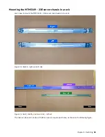
- Inner CMA arm connector
B
- Inner rail connector
C
- Outer CMA arm connector
D
- Outer rail connector
E
- CMA body connector
F
- CMA body rail connector
Figure 44. Cable management assembly installation
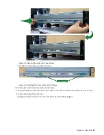
3. To change the direction of the arm for use on the opposite side of the enclosure, press the release
buttons on the outside of the CMA elbow and rotate the arm 180 degrees.
Figure 45. CMA release buttons
4. Slide the inner CMA arm connector (A) onto the lower right inner rail connector (B) as shown in the
following figure.
Chapter 4. Installing 67
Summary of Contents for 6.1.8.2
Page 8: ...viii...
Page 20: ...xx IBM Storage Scale System Utility Node Hardware Planning and Installation Guide...
Page 90: ...70 IBM Storage Scale System Utility Node Hardware Planning and Installation Guide...
Page 96: ...76 IBM Storage Scale System Utility Node Hardware Planning and Installation Guide...
Page 100: ...80 IBM Storage Scale System Utility Node Hardware Planning and Installation Guide...
Page 102: ...82 IBM Storage Scale System Utility Node Hardware Planning and Installation Guide...
Page 110: ...90 IBM Storage Scale System Utility Node Hardware Planning and Installation Guide...
Page 112: ...92 IBM Storage Scale System Utility Node Hardware Planning and Installation Guide...
Page 113: ......
Page 114: ...IBM Product Number 5765 DME 5765 DAE SC28 3469 00...