
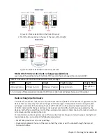


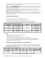


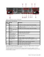


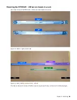


Figure 17. Sample illustration to show space around the rack
For the utility node, use the recommended measurements that are given in the following table.
Table 16. Service clearance requirements
Front
1
Back
915 mm (36 in.)
915 mm (36 in.)
1
Storage racks require larger service clearances in the front of the rack.
For more information about the layout of the room, see Computer room layout.
See the Site preparation and physical planning section to help you prepare your physical site for the
installation of a utility node.
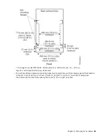
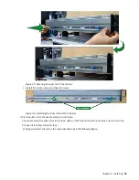
Additional space requirements
Ensure that these additional space requirements, as shown in the following table, are available around the
server.
Table 17. Clearances
Location
Additional space requirements
Reason
Left and right sides
50 mm (2 in.)
Cooling air flow
Back
Minimum: 100 mm (4 in.)
Cable exit
46 IBM Storage Scale System Utility Node: Hardware Planning and Installation Guide
Summary of Contents for 6.1.8.2
Page 8: ...viii...
Page 20: ...xx IBM Storage Scale System Utility Node Hardware Planning and Installation Guide...
Page 90: ...70 IBM Storage Scale System Utility Node Hardware Planning and Installation Guide...
Page 96: ...76 IBM Storage Scale System Utility Node Hardware Planning and Installation Guide...
Page 100: ...80 IBM Storage Scale System Utility Node Hardware Planning and Installation Guide...
Page 102: ...82 IBM Storage Scale System Utility Node Hardware Planning and Installation Guide...
Page 110: ...90 IBM Storage Scale System Utility Node Hardware Planning and Installation Guide...
Page 112: ...92 IBM Storage Scale System Utility Node Hardware Planning and Installation Guide...
Page 113: ......
Page 114: ...IBM Product Number 5765 DME 5765 DAE SC28 3469 00...