background image

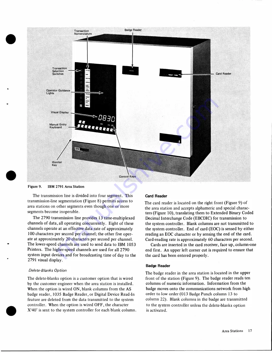
Transaction

Nomenclature

Badge  Reader

Operator  Guidance 
Lights

Manual  Entry 

Keyboard

Card  Reader

Control  Keys

Figure 9. 

IBM  2791  Area Station

The  transmission line  is divided into  four segment.  This 

transmission-line  segmentation (Figure  8)  permits access to 
area stations on  other segments even  though one  or more 
segments become  inoperable.

The  2790 transmission  line provides  13  time-multiplexed 

channels of data, all operating concurrently.  Eight  of these 
channels operate at  an effective  data rate  of approximately 

100 characters per  second  per  channel; the  other five  oper­

ate  at  approximately  20 characters per second per  channel. 
The lower-speed channels are  used to send data to  IBM  1053 

Printers.  The  higher-speed  channels are  used for all 2790 

system input devices and for broadcasting time of day to the 
2791  visual display.

Delete-Blanks Option

The  delete-blanks option  is a customer  option that  is wired 
by  the  customer engineer when the  area station is installed. 
When the  option is wired ON, blank columns from the AS 
badge  reader,  1035  Badge  Reader, or Digital Device  Read-In 
feature  are  deleted from the  data transmitted  to the  system 
controller.  When the  option is wired OFF, the  character 
X‘40’  is sent  to  the  system controller for each blank column.

Card  Reader

The  card  reader is located on the  right front  (Figure  9)  of 

the  area station  and accepts alphameric and  special charac­

ters (Figure  10), translating them to  Extended Binary Coded 
Decimal Interchange  Code (EBCDIC) for transmission to 
the system controller.  Blank columns are  not transmitted to 
the  system controller.  End of card (EOC) is sensed by either 
reading an EOC  character or by sensing the end  of the  card. 
Card-reading rate is approximately 60 characters per second.

Cards are inserted in the  card receiver, face up, column-one 

end first.  An upper left  corner  cut is required to ensure  that 
the  card has been entered properly.

Badge  Reader

The  badge reader in the  area station is located in  the  upper 
front  of the  station (Figure  9).  The badge  reader reads ten 

columns of numeric information.  Information from the 
badge  moves onto the  communications network from high 
order to low  order (013  Badge Punch column  13  to 
column 22).  Blank columns in the badge  are  transmitted 

to  the  system controller unless the  delete-blanks  option 
is activated.

Area Stations 

17

Summary of Contents for 2790

Page 1: ...also be used as the system controller is not described in this manual Information about the following units is included in this publication IBM 2715 Transmission Control Unit IBM 2796 Data Entry Unit...

Page 2: ...e 2790 system see Systems Reference Library manuals IBM System 360 Operating System Basic Telecommunications Access Method GC30 2004 IBM System 360 Disk Operating System Basic Tele communications Acce...

Page 3: ...l Adapter Standard on 2715 Model 1 31 C om m ands 32 Binary Synchronous Communications Adapter Standard on 2715 Model 2 33 Real Time Clock R T C 35 Day Number 35 CE Operator P a n el 35 2790 A d a p t...

Page 4: ...2715 Transmission Control U n i t 18 Line Transfer S w it c h Figure Title Page 19 Line Transfer Switch Third U nit 29 20 Point to Point Line Initialization Examples 33 1 21 Multipoint Line Initializa...

Page 5: ...te binary synchronous trans mission line attachment Either an IBM 2715 Transmission Control Unit or an IBM 1800 Data Acquisition and Control System with an 1800 2790 Adapter may be used as the system...

Page 6: ...ication System supplies the latest information to the data processing center thus diminishing the time gap between the organization of data and its availability for use Some of the applications of the...

Page 7: ...quantity and stock room location is inserted in the DEU Ten columns of numeric data together with variable fields are transmitted to the data processing system updating the parts inventory Production...

Page 8: ......

Page 9: ...DEU includes the following features Badge Card Reader A badge card reader located on the top of the DEU reads ten digits of numeric information punched as shown in Figure 5 The badge card reader can r...

Page 10: ...12 digits of data plus transaction header information see Figure 6 Digit 1 Type of DEU Digit 2 Setting of right hand rotary switch Note Such information as device address area station address and lef...

Page 11: ...tion of these switches is optional except for digits OX X is any right hand switch setting which are reserved for clearing and testing the oper ation of the unit A holder is provided on the front cove...

Page 12: ...he operator initiates the request for service by positioning the lever in the latched position which is indicated by green in the entry flag window The request lever cannot be fully positioned if the...

Page 13: ...pper right hand rotary switch Digits 3 through 12 Contents of card or badge Blanks are transmitted for these positions if a card or badge is not entered as part of the data entry Digit 13 Setting of l...

Page 14: ...the nine transaction codes on the left hand rotary switch by using transaction expansion Transaction expansion allows the right hand upper right hand for 2796 rotary switch to supply a second digit to...

Page 15: ...and terminating at the TCU in a serial loop configu ration Area Station Nomenclature Commonly used words with a specific meaning for the 2790 system are Data Entry A single block of data entered by an...

Page 16: ...Area station transactions selected by transaction expan sion may be multiple input data entries Note Digit zero is an invalid transaction expansion digit Transaction expansion is a prerequisite for m...

Page 17: ...r Digital Device Read In feature are deleted from the data transmitted to the system controller When the option is wired OFF the character X 40 is sent to the system controller for each blank column C...

Page 18: ...11 A7 y 11 0 8 1010 1000 A8 z 11 0 9 1010 1001 A9 9 12 2 8 0100 1010 4A 12 3 8 0100 1011 4B 12 5 8 0100 1101 4D 12 6 8 0100 1110 4E 1 12 7 8 0100 1111 4F 12 0101 0000 50 11 2 8 0101 1010 5A 11 3 8 010...

Page 19: ...nd Additional data entries from the keyboard may be chained into one transaction under 2715 user table control trans action list steps Visual Display A six position visual readout is located on the lo...

Page 20: ...lear key has been pressed Area Station Addresses The area stations are assigned addresses when they are in stalled The area station AS addresses are 80 hex through E3 hex The AS sends its address with...

Page 21: ...nt Optional on 2791 Model 1 Only The 1035 Badge Reader Attachment allows the connection of as many as three remote badge readers to each area station Area Station Register Area stations are attached t...

Page 22: ...NTER DEPT NO 3 DIGITS INSERT BLUE CARD ENTER SHIFT 1 DIGIT INSERT BLUE CARD ENTER SHIFT I DIGIT INSERT CARD ENTER QUANTITY 1 6 DIGITS INSERT CARD ENTER QUANTITY 1 6 DIGITS SPACE ALLOCATED FOR WORDS 27...

Page 23: ...ns 76 77 78 79 80 First Punched Card Column Card reader does not transmit blanks to Controller Area Station Badge Reader Badge Data Entry EBCDIC 4 5 6 7 8 Column 80 entered here if all 80 columns are...

Page 24: ...A 1 1 0 0 0 0 0 1 Cl B 1 1 Q 0 0 0 1 0 C2 C 1 1 0 0 0 0 1 1 C3 D 1 1 0 0 0 10 0 C4 E 1 1 0 0 0 1 0 1 C5 F 1 1 0 0 0 1 1 0 C6 G 1 1 0 0 0 1 1 1 C7 H 1 1 0 0 1 0 0 0 C8 1 1 1 0 0 1 0 0 1 C9 J 1 1 0 1 0...

Page 25: ...tes with these tables to provide control and data service for attached 2790 terminals Data assembled from 2790 terminals may be routed on a priority basis to System 360 when the 2715 is operating in t...

Page 26: ...d into completed transactions by the 2715 and then transferred to System 360 in message blocks up to a maxi mum of 612 bytes long On Line Off Line In this mode the 2715 TCU collects data from 2790 ter...

Page 27: ...data entry unit to another attached area station equipped with IBM 1053 Printer is required independent of the System 360 operation A transaction entered at a 2791 Area Station or a 2795 or 2796 Data...

Page 28: ...ol digit 0 9 I 3 Enter text optional 4 Press EOT end of text The line bid initiates the connection with the 2715 and allows the 2740 operator to enter the desired control char I acter The control char...

Page 29: ...the end of text without any user inserted control char acter 2715 to 2740 Control Messages For control between the 2715 and the 2740 the user may specify 2740 transaction routing when he assembles the...

Page 30: ...the 2715 is command free it will signal channel end and device end as a status response to initial selection and the TPS will return to the neutral state immediately following the fall of operational...

Page 31: ...data and status transfer via hard ware Command Compatibility 2715 2701 Compatible Usage of the following commands is compatible between the 2715 and the 2701 Read Write Prepare Sense No Op Test I O En...

Page 32: ...d status 2 Busy indicates that the 2715 has not completed the last command Test I O relieves the 2715 of any pending or stacked status Enable Disable Set Mode For compatibility these commands are acce...

Page 33: ...operation requires Expanded Capability feature Non Switched or switched with network previously established Transmitting Station Sends ENQ DLE STX text DLE ETX Listening Station Sends ACK0 or NAK or W...

Page 34: ...ceives a signal the 2715 monitors for an identi fication sequence If no identification sequence is received within 20 seconds the 2715 disables the line timeout con dition If the identification sequen...

Page 35: ...tion header will contain time stamp The time stamp consists of four EBCDIC characters that specify hours and minutes For 2715 to System 360 messages the time stamp contains the value of the clock when...

Page 36: ...pushbutton is pressed with the Panel Select switch in this position the 2715 goes into off line diagnostic control mode The off line diag nostics can be requested when the Diagnostic Control indicato...

Page 37: ...5 X 0086 X 0088 X 0089 X 008A X 008B XC 008C X 008D X 008E X 008F X 0095 X 0096 X 0097 X 0098 X 009A X 009B X 009C X 00A1 X 00A2 X 0FF1 X 0FF2 X 0FF3 Invalid panel request Invalid panel request with C...

Page 38: ...Figure 23 Transmission Line Utilization Chart 03 04 05 06 08 10 2 2 5 3 4 5 6 7 8 9 1 0 1 5 2 2 5 3 Entries Per Second 5 6 7 8 9 10 15 20 25 30 40 50 60 70 80 90100...

Page 39: ...e interval Possibly other data traffic com bined with attendance recording traffic may exceed full load traffic for a short period of time thus increasing the time required to clock out the employees...

Page 40: ...he 2715 are trans ferred to the 2740 terminal or the 1053 printer for printout or to the 2715 maintenance section for internal control This System 360 output data is never stored on the 2715 disk All...

Page 41: ...by a control trans action from the System 360 When read deferred data mode is set and the 2715 has no priority data deferred data is sent to the System 360 as soon as a full block of data is on the di...

Page 42: ...stem 360 message length is limited to a maximum of 612 bytes mes sage header 5 bytes transaction header s 8 bytes and text The message header format is defined as follows First Second and Third Byte D...

Page 43: ...addition to being routed to a 1053 the message may be logged on the 2740 and or sent to the CPU as deferred or priority data Message routing provides for the handling of implicit and explicit address...

Page 44: ...re responses are sent as a function of where the request origi nated Note that the 2715 sends a response message to the System 360 whenever a panel operator request causes the 2790 system to be reconf...

Page 45: ...ial Error Log C C D7 P _ D 7 D 7 F 0 Reinitialize Disk C D8 Q On Line Core Dump T _ R Core address 4 Set Day C P E2 S 3 digit day number 4 F Any numeric characters _ _ _ E 2 F 0 Monitor Day C P E3 T _...

Page 46: ...a station causing it to go on line The response is printed on the 2740 if present prior to being sent to the CPU Request Format System 360 Standard format with dj containing the area station address C...

Page 47: ...lready bypassed or was requested to be bypassed X F0F2 Segment had to be bypassed because nothing was received from segment X F0F3 Segment has to be bypassed because it could not successfully pass 500...

Page 48: ...ard format Response Format a Positive No response is generated as a direct result of executing this control request However when the read deferred data mode is reset automatically see X C5 Set Read De...

Page 49: ...bles are used by the 2715 until the user reconfigures his system with another user table load The 2715 must be preconditioned with a stop 2790 input control request or an ICPL No other control request...

Page 50: ...red restart number log d3 and d4 contain the priority restart number log See Restart Number Logging CE Panel Standard format with no additional data used Response Format System 360 requests Standard f...

Page 51: ...ata Send Data 5 Read Response Response X C5 to Def Data 6 a Reinitialize 2715 DiskX D8 Initialize Disk b Read Response Send X D8 Response c Set Restart number Log to Zero 7 Set Day Optional X E2 Execu...

Page 52: ...tors the Real Time Clock that time stamps all user data at the transaction level Request Format System 360 and CE Panel Standard format with no additional data required Response Format System 360 Stan...

Page 53: ...to be written on disk 4 X 19 2790 input not stopped 2790 ERP Message Format This message is generated and sent to System 360 and 2740 anytime the 2715 executes an ERP on the 2790 This message has as i...

Page 54: ...ero when the 2715 is ICPL ed Core Storage The basic 2715 uses a 16K byte ferrite core storage unit for storing control programs and for message buffering The core storage unit has a word width of 18 b...

Page 55: ...educing channel speed If the request is made during a high traffic period nearly all disk time can be spent putting data on the disk and the read operation will proceed very slowly Therefore for best...

Page 56: ...V IT...

Page 57: ...eleases the badge by pressing the Clear switch The 2715 discards the error data Note The 2790 system reliability assumes that a non blank character length count check is performed by either the 2715 o...

Page 58: ...this condition by pressing the Clear button This extinguishes the error lamp and releases the media card or badge Guidance reverts to that designated for the step in error The operator may retry the s...

Page 59: ...ense command must be performed to obtain further information about the error interrupt Hardware Detected Errors System 360 Interface I O Bus Out Check All information transferred on I O bus out requir...

Page 60: ......

Page 61: ...for later transmittal Transactions may be blocked together to make one longer message or be sent singly This function is performed automatically by the 2715 microcode on 2715 to Sys tem 360 messages...

Page 62: ...step number from the area station sequence table is used to find the correct step from the transaction list table TR List table The transaction list step contains the information necessary for the mi...

Page 63: ...0 AS Sequence 80 81 E3 DEU Sequence TC TC TC TG Table TG 2 TG 3 TG 63 Step No TR List Table TG 1 1 List 4 2 List 1 3 List 2 ______________ 9 List 5 1 List 1 2 List 2 3 List 3 4 List 4 9 List 6 1 List...

Page 64: ...Address If the printed message may go to one of several printers and the area station address is to be entered by the operator check this column Fixed Address If the printed message will always go to...

Page 65: ...uidance Enter the guidance light to be used for operator instruction in case the digit is not correct Multiple Entries Area Station Only Enter an M in this column if this data entry is to accom modate...

Page 66: ...on and Data Entry Unit Table Area Station Identification Transaction Group Name Number of DEU s Attached 8 1 6 2 4 32 Comments Location Nos 00 99 Area Station Data Entry Units Figure 32 AS and DEU Tab...

Page 67: ...Figure 33 Transaction Group Table Form Programming Considerations 67...

Page 68: ...ice Length Check Digit Check M u 1 E t n i t P r 1 y e Message Text Number D s k C P u 2 7 4 0 S e 1 e c t e d F i X e d Badge Card Manual OEM G u d a n c e L e n g t h G u d a n c e P 0 s 1 t i o n D...

Page 69: ...onitor Key Oor 1 1 2 3 Punched Card Columnst 76 77 78 79 80 Card Column Area Station Badge Reader Badge Data Entry EBCDIC 2 3 4 5 6 7 8 columns are punched 9 10 11 Monitor Badge Columns Key Oor 1 13 1...

Page 70: ......

Page 71: ...System 360 assembler macro instruction DLE Binary synchronous line control character Data Link Escape DOS Disk Operating System 360 EBCDIC Extended Binary Coded Decimal Interchange Code ENQ Line cont...

Page 72: ...n the transaction was received The time is recorded in 24 hour form as EBCDIC characters TPS Two Processor Switch Transaction A sequence of interrelated data entries entered by the operator at an Area...

Page 73: ...C text replies 33 BTAM modifications for 2715 operation 61 bypass area station 46 bypass segment 46 card codes AS 18 2795 10 2796 13 Card In Card Reader indicator 20 card punching 10 card reader 17 ca...

Page 74: ...line 58 2791 Area Station 57 2795 2796 Data Entry Unit 57 ETB 33 ETX 33 examples multipoint line initialization 34 point to point line initialization 33 utilization 39 2740 printout 47 2740 printout...

Page 75: ...ositive response CPU request 46 positive response 2715 request 44 Power Off switch 35 Power On switch 35 Prepare command 32 procedures error 57 2740 control request 29 production control 7 programming...

Page 76: ...actions 40 United Kingdom GPO modem 30 unsolicited responses 44 user job planning forms 62 user table 62 user table assembly 61 user table load 49 utilization examples 39 utilization formulas 39 visua...

Page 77: ...enter lines for each transaction Nomenclature for each guidance light is to be within appropriate box 31 30 29 28 Release 27 26 25 24 23 22 21 20 19 18 17 16 15 14 13 12 11 10 09 08 07 06 05 04 03 02...

Page 78: ......

Page 79: ...nter lines for each transaction Nomenclature for each guidance light is to be within appropriate box 31 30 29 28 h Release 27 26 25 24 23 22 21 20 19 18 17 16 15 14 13 12 11 10 09 08 07 06 05 04 03 02...

Page 80: ...t...

Page 81: ...enter lines for each transaction Nomenclature for each guidance light is to be within appropriate box 31 30 29 28 Release 27 26 25 24 23 22 21 20 19 18 17 16 15 14 13 12 11 10 09 08 07 06 05 04 03 02...

Page 82: ...9...

Page 83: ...enter lines for each transaction Nomenclature for each guidance light is to be within appropriate box 31 30 29 28 Release 27 26 25 24 23 22 21 20 19 18 17 16 15 14 13 12 11 10 09 08 07 06 05 04 03 02...

Page 84: ...9...

Page 85: ...4...

Page 86: ...ines Corporation Data Processing Division 112 East Post Road White Plains N Y 10601 USA Only IBMWorld Trade Corporation 821 United Nations Plaza New York New York 10017 International NJ CO O o C D C D...

Page 87: ...wn experience rate this publication As a reference source Very Good Fair Good Poor Very Poor As a text Very Good Fair Poor Very Good Poor What is your occupation We would appreciate your other comment...

Page 88: ...g your IBM system should be directed to your IBM representative or to the IBM sales office serving your locality I Fold B U S I N E S S R E P L Y M A I L NO POSTAGE STAMP NECESSARY IF MAILED IN U S A...

Reviews: