


Hardware Configuration
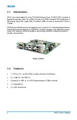
IP417
User’s Manual
15
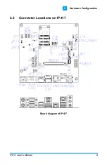
2
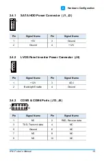
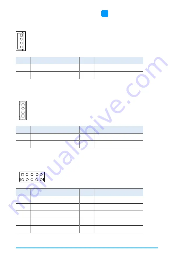
2.4.1
SATA HDD Power Connector (J1, J2)
1
Pin
Signal Name
Pin
Signal Name
1
+5V
3
Ground
2
Ground
4
+12V
2.4.2
LVDS Panel Inverter Power Connector (J6)
1
Pin
Signal Name
Pin
Signal Name
1
+12V
3
ADJ
2
Backlight Enable
4
Ground
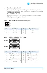
2.4.3
COM3 & COM4 Ports (J13, J8)
1
2
9
10
Pin
Signal Name
Pin
Signal Name
1
NC
2
RXD, Receive data
3
TXD, Transmit data
4
NC
5
Ground
6
NC
7
NC
8
NC
9
NC
10
NC
Summary of Contents for IP417
Page 1: ...IP417 Mini ITX COM Express Type 10 R3 0 Carrier Board User s Manual Version 1 0 July 2019...
Page 8: ...viii IP417 User s Manual This page is intentionally left blank...
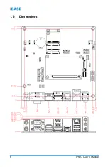
Page 14: ...6 IP417 User s Manual 1 5 Dimensions...
Page 28: ...20 IP417 User s Manual This page is intentionally left blank...


