background image


ARD-042-N 

All-in-One Bar-Type   

Digital Signage Display 


User’

s Manual 


Version 1.0 

(Dec. 2018)


Summary of Contents for ARD-042-N

Page 1: ...ARD 042 N All in One Bar Type Digital Signage Display User s Manual Version 1 0 Dec 2018...

Page 2: ...to the products described in this document without prior notice Every effort has been made to ensure the information in the document is correct however IBASE does not guarantee this document is error...

Page 3: ...cy energy and if not installed and used in accordance with manufacturer s instructions may cause harmful interference to radio communications WEEE This product must not be disposed of as normal househ...

Page 4: ...ents or diluted alcohol to clean the device chassis with a cloth Then wipe the chassis with a dry cloth Vacuum dust and particles from the vents by using a computer vacuum cleaner WARNING Attention du...

Page 5: ...TO MISUSE ACCIDENT IMPROPER INSTALLATION OR UNAUTHORIZED REPAIR SHALL BE TREATED AS OUT OF WARRANTY AND CUSTOMERS SHALL BE BILLED FOR REPAIR AND SHIPPING CHARGES Technical Support Services 1 Visit th...

Page 6: ...ng Brackets Installation 9 2 2 Setting the Jumpers 10 2 2 1 How to Set Jumpers 10 2 3 Jumper Connector Locations on Motherboard 11 2 4 Jumpers Quick Reference 12 2 4 1 LVDS Panel Brightness Selection...

Page 7: ...tion 29 4 2 BIOS Setup 29 4 3 Main Settings 30 4 4 Advanced Settings 31 4 4 1 ACPI Settings 32 4 4 2 LVDS eDP DP Configuration 33 4 4 3 Fintek Super IO Configuration 34 4 4 4 Fintek Super IO Hardware...

Page 8: ...1 Chapter 1 General Information The information provided in this chapter includes Features Packing List Specifications Overview Dimensions...

Page 9: ...menu boards 1 2 Features Ruggedized fanless and compact design 42 color TFT active matrix wide LCD with optimum resolution 1920 x 480 Intel Pentium N4200 1 1 2 5 GHz with Intel SoC integrated Gen 9 1...

Page 10: ...k F81964 Storage 1 x mSATA Audio Codec Intel SoC built in HD audio controller Realtek ALC283QHD codec with speaker amplifier Power Supply 180W power adapter BIOS AMI BIOS Watchdog Watchdog Timer 256 s...

Page 11: ...096 x 2160 at 60 Hz LAN 2 x RJ45 GbE LAN USB 4 x USB 3 0 Serial 1 x COM Port RS 232 422 485 jumperless selection Expansion 1 x M 2 B3042 Slot with PCIe x1 USB and SATA Environment Temperature Operatin...

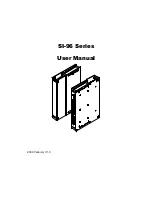
Page 12: ...General Information ARD 042 N User Manual 5 1 W 1 5 Dimensions Unit mm...

Page 13: ...6 Chapter 2 Hardware Configuration The information provided in this chapter includes Essential installations before you begin Information and locations of connectors...

Page 14: ...es mSATA card and wireless card you need to open the rear device cover Follow the instructions below 1 Remove 7 screws as indicated below to open the cover marked in yellow below with the motherboard...

Page 15: ...ht position until the clips of the slot click to hold the module in place when the module touches the bottom of the slot To remove the module press the clips outwards with both hands 2 1 2 Mini PCIe m...

Page 16: ...e brackets ensure that you have enough room for power and signal cable routing The method of mounting must be able to support weight of the system plus the suspend weight of all the cables to be attac...

Page 17: ...s with a non conductive base mounted on the circuit board Jumper caps are used to have the functions and features enabled or disabled If a jumper has 3 pins you can connect either PIN1 to PIN2 or PIN2...

Page 18: ...J5 JP2 JP4 JP3 J1 J3 J6 BAT1 J10 J4 J7 J21 JP6 JP5 JP7 J16 J17 J20 J12 J13 CN3 CN2 J11 JP1 J2 204 74 1 71 72 73 2 203 1 2 74 71 72 73 204 203 1 1 1 30 1 1 1 1 1 2 19 20 2 19 20 1 7 8 1 2 11 12 1 1 1...

Page 19: ...1 12 LVDS Planel Power Selection JP2 13 eDP Panel Power Selection JP3 13 eDP LVDS Panel Seelction JP4 14 ATX AT Power Selection JP5 14 Clearing CMOS Data JP6 15 Clearing ME Register JP7 15 Factory Use...

Page 20: ...RD 042 N User Manual 13 2 2 4 2 LVDS Panel Power Selection JP2 Function Pin closed Illustration 3 3V default 1 2 5V 2 3 2 4 3 eDP Panel Power Selection JP3 Function Pin closed Illustration 3 3V defaul...

Page 21: ...2 N User Manual 2 4 4 eDP LVDS Panel Selection JP4 Function Pin closed Illustration eDP 1 2 LVDS default 2 3 2 4 5 ATX AT Power Selection JP5 Function Pin closed Illustration ATX default 1 2 AT 2 3 1...

Page 22: ...N User Manual 15 2 2 4 6 Clearing CMOS Data JP6 Function Pin closed Illustration Normal default 1 2 Clear CMOS 2 3 2 4 7 Clearing ME Register JP7 Function Pin closed Illustration Normal default 1 2 Cl...

Page 23: ...tal I O Connector J18 20 DC Power Input Connector J19 21 SATA III Connector CN2 shared with M 2 B key CN3 shared with mSATA LAN Ports CN4 USB 3 0 Ports CN5 CN6 DisplayPort CN8 HDMI Port CN9 LCD Backli...

Page 24: ...sigment 1 NC 16 Ground 2 BL_Power 17 NC 3 BL_Power 18 Panel_VDD 4 BL_Power 19 Panel_VDD 5 BL_Power 20 Ground 6 NC 21 AUX_N 7 NC 22 AUX_P 8 BRIGHTNESS 23 Ground 9 Bklt_en 24 TX0_P 10 Ground 25 TX0_N 11...

Page 25: ...set ready 6 DCD Data carrier detect 2 Ground 7 DTR Data terminal ready 3 Ground 8 CTS Clear to send 4 TX Transmit 9 RTS Request to send 5 RX Receive 10 RI Ring Indicator Pin Assignment RS 232 RS 422...

Page 26: ...Hardware Configuration ARD 042 N User Manual 19 2 2 5 3 SATA HDD Power Connector J10 Pin Assigment Pin Assigment 1 5V 3 Ground 2 Ground 4 12V 1...

Page 27: ...ta carrier detect 2 RXD Receive data 3 TXD Transmit data 4 DTR Data terminal ready 5 Ground 6 DSR Data set ready 7 RTS Request to send 8 CTS Clear to send 9 RI Ring indicator 10 Not Used 2 5 5 Digital...

Page 28: ...Hardware Configuration ARD 042 N User Manual 21 2 2 5 6 DC Power Input Connector J19 Pin Assigment Pin Assigment 1 9V 36V 2 Ground 1...

Page 29: ...on provided in this chapter includes Intel Chipset Software Installation Utility Intel Graphics Driver Installation HD Audio Driver Installation Intel Trusted Execution Engine Installation Intel USB 3...

Page 30: ...operating system you must install the Intel Chipset Software Installation Utility first before proceeding with the drivers installation 3 2 Intel Chipset Software Installation Utility The Intel Chipse...

Page 31: ...ffect 3 3 Intel Graphics Driver Installation 1 Run the Setup exe file 2 When the Welcome screen appears click Next to continue 3 Click Yes to agree with the license agreement and continue the installa...

Page 32: ...screen of the InstallShield Wizard click Next for installation 3 Click Next until the installation starts 4 The driver has been completely installed Restart the computer for changes to take effect 3 5...

Page 33: ...er and for changes to take effect 3 6 Intel Serial I O Drivers Installation 1 Run the Setup exe file 2 When the Welcome screen appears click Next 3 Accept the license agreement and click Next 4 After...

Page 34: ...click Next 3 Accept the license agreement and click Next to continue 4 On the Setup Options screen click the checkbox to select the desired driver s for installation Then click Next to continue 5 Whe...

Page 35: ...apter describes the different settings available in the AMI BIOS that comes with the board The topics covered in this chapter are as follows Main Settings Advanced Settings Chipset Settings Security S...

Page 36: ...Test will continue with its test routines thus preventing you from invoking the Setup If you still need to enter Setup restart the system by pressing the Reset button or simultaneously pressing the C...

Page 37: ...N User Manual 4 3 Main Settings BIOS Setting Description System Date Sets the date Use the Tab key to switch between the data elements System Time Set the time Use the Tab key to switch between the da...

Page 38: ...BIOS Setup ARD 042 N User Manual 31 4 4 4 Advanced Settings This section allows you to configure improve your system and allows you to set up some system features according to your preference...

Page 39: ...ion Enable Hibernation Enables Disables the system ability to hibernate OS S4 Sleep State This option may be not effective with some OS ACPI Sleep State Selects an ACPI sleep state Suspend Disabled or...

Page 40: ...ort Enables Disables LVDS eDP DP Panel Color Depth Selects a panel color depth as 24 JEIDA bit LVDS Channel Type Sets the LVDS channel type as dual channel Panel Type Selects the resolution S420HW62 1...

Page 41: ...ion Standby Power on S5 Enables Disables to provide the standby power for devices Options All Enable Enable Ethernet for WOL All Disable Serial Ports Configuration Sets parameters of serial ports Enab...

Page 42: ...Settings Selects an optimal settings for Super IO device Options Auto IO 3F8h IRQ 4 IO 3F8h IRQ 3 4 5 6 7 9 10 11 12 IO 2F8h IRQ 3 4 5 6 7 9 10 11 12 IO 3E8h IRQ 3 4 5 6 7 9 10 11 12 IO 2E8h IRQ 3 4 5...

Page 43: ...fields are the parameters of the hardware monitoring function feature of the motherboard The values are read only values as monitored by the system and show the PC health status CPU Shutdown Temperatu...

Page 44: ...BIOS Setup ARD 042 N User Manual 37 4 4 4 5 M 2 Setup BIOS Setting Description M 2 Select Selects the M 2 interface as SATA or PCIe...

Page 45: ...Description Socket 0 CPU Information Displays the socket specific CPU information CPU Power Management Allows you to enable disable Turbo Mode Active Processor Cores Enables Disables the cores in the...

Page 46: ...BIOS Setup ARD 042 N User Manual 39 4 4 4 7 AMI Graphic Output Protocol Policy BIOS Setting Description Output Select Outputs through HDMI interface...

Page 47: ...s Disables IPv4 HTTP Boot Support If disabled Ipv4 HTTP boot option will not be created IPv6 PXE Support Enables Disables IPv6 PXE Boot Support If disabled Ipv4 PXE boot option will not be created IPv...

Page 48: ...uted above 1 MB INT19 Trap Response Sets how BIOS reacts on INT19 trap by Option ROM Immediate executes the trap right away Postponed executes the trap during legacy boot Boot option filter Controls t...

Page 49: ...d be claimed by XHCI driver USB Mass Storage Driver Support Enables Disables the support for USB mass storage driver USB Transfer time out The time out value 1 5 10 20 secs for Control Bulk and Interr...

Page 50: ...BIOS Setup ARD 042 N User Manual 43 4 4 5 Chipset Settings 4 5 1 North Bridge...

Page 51: ...44 ARD 042 N User Manual 4 5 2 South Cluster Configuration 4 5 2 1 HD Audio Configuration...

Page 52: ...on BIOS Setting Description PCI Express Root Port 1 6 Accesses the control of the PCI Express Root Port BIOS Setting Description PCI Express Root Port Enables Disables the PCIe root port Auto To disab...

Page 53: ...ptions Disables L1 1 L1 2 L1 1 L1 2 PME SCI Enables Disables PME SCI PCIe Speed Configures the PCIe speed 4 5 2 3 SATA Drivers BIOS Setting Description Chipset SATA Enables Disables the Chipset SATA C...

Page 54: ...ed up in OS Do NOT disable it unless for debug purpose USB VBUS VBUS should be ON in HOST mode It should be OFF in OTG device mode USB HSIC1 Support Enables Disables USB HSIC1 USB SSIC1 Support Enable...

Page 55: ...48 ARD 042 N User Manual 4 6 Security Settings BIOS Setting Description Setup Administrator Password Sets an administrator password for the setup utility User Password Sets a user password...

Page 56: ...e waiting Bootup NumLock State Selects the keyboard NumLock state Quiet Boot Enables Disables Quiet Boot option New Boot Option Policy Controls the placement of newly detected UEFI boot options Option...

Page 57: ...ter saving the changes Discard Changes and Reset Resets system setup without saving any changes Save Changes Saves changes done so far to any of the setup options Discard Changes Discards changes done...

Page 58: ...ppendix This section provides the mapping addresses of peripheral devices and the sample code of watchdog timer configuration I O Port Address Map Interrupt Request Lines IRQ Watchdog Timer Configurat...

Page 59: ...00067 Motherboard resources 0x00000070 0x00000070 Motherboard resources 0x00000070 0x00000070 System CMOS real time clock 0x00000080 0x0000008F Motherboard resources 0x00000092 0x00000092 Motherboard...

Page 60: ...mable interrupt controller 0x0000003C 0x0000003D Programmable interrupt controller 0x000000A0 0x000000A1 Programmable interrupt controller 0x000000A4 0x000000A5 Programmable interrupt controller 0x000...

Page 61: ...mer IRQ 10 Communications Port COM4 IRQ 14 Intel R Serial IO GPIO Host Controller INT3452 IRQ 25 High Definition Audio Controller IRQ 35 PCI Data Acquisition and Signal Processing Controller IRQ 36 PC...

Page 62: ...regular intervals before the timer counts to zero Sample Code THIS CODE AND INFORMATION IS PROVIDED AS IS WITHOUT WARRANTY OF ANY KIND EITHER EXPRESSED OR IMPLIED INCLUDING BUT NOT LIMITED TO THE IMPL...

Page 63: ...ic device 7 Set_F81964_Reg 0x30 0x01 enable timer bBuf Get_F81964_Reg 0xF5 bBuf 0x0F bBuf 0x52 Set_F81964_Reg 0xF5 bBuf count mode is second Set_F81964_Reg 0xF6 interval set timer bBuf Get_F81964_Reg...

Page 64: ...81964_BASE void Unlock_F81964 void void Lock_F81964 void unsigned int Init_F81964 void unsigned int result unsigned char ucDid F81964_BASE 0x4E result F81964_BASE ucDid Get_F81964_Reg 0x20 if ucDid 0x...

Page 65: ...Get_F81964_Reg unsigned char REG unsigned char Result Unlock_F81964 outportb F81964_INDEX_PORT REG Result inportb F81964_DATA_PORT Lock_F81964 return Result THIS CODE AND INFORMATION IS PROVIDED AS I...

Page 66: ...ppendix ARD 042 N User Manual 59 unsigned int Init_F81964 void void Set_F81964_LD unsigned char void Set_F81964_Reg unsigned char unsigned char unsigned char Get_F81964_Reg unsigned char endif F81964_...

Reviews: