


i3-TRNG-ACCESSORIES-
UIO8
.indd
Rev. 200510
Universal Input/Output Device
UIO8
User Manual
complete range of i3 product quick guides and manuals.
Contact our Technical Support team at:
1.877.877.7241
or
if you have any questions or
concerns regarding camera installation or if you require software
services or support.
Thank you for purchasing an i3 UIO8 LAN Inputs and Output Peripheral Device.
UIO8 has been designed to support two different functions: a single-reader card access
controller board or a universal I/O controller with 4 inputs & 4 outputs.
When used as an I/O Contoller device, i3’s UI08 may be integrated with the i3’s SRX-
Pro DVR/NVR system via LAN. SRX-Pro Server will detect and connect to all UIO8 devices
connected to Local Area Network. Each UIO8 device supports 4 inputs and 4 outputs and
can control PTZ cameras through the TCP/IP (network). SRX-Pro Server can connect to
a total of 16 individual UIO8 devices supporting up to a maximum of 64 inputs and 64
outputs.
UIO8 can be powered with a 24~36VAC power source or via PoE Switch on the
network. UIO8 device, in turn, offers a 12VDC output, to power other connected devices
such as strobe light, buzzer, alarm etc., making for a more convenient and cost-efficient
installation. UIO8 may also be integrated with i3’s CMS sensor input, which adds further
reporting and monitoring capabilities to i3 International’s CMS Site Info module and Alert
Centre application.
If the system needs to be modified or repaired, contact a certified i3 International
Dealer/Installer. When serviced by unauthorized technician, the system warranty will be
voided. Should you have any problems or questions regarding our products, contact your
local Dealer/Installer.
Precautions
Installation and serving should be performed only by qualified and experienced technicians
to conform to all local codes and to maintain your warranty.
When installing your UIO8 device be sure to avoid:
•
excessive heat, such as direct sunlight or heating appliances
•
contaminants such as dust and smoke
•
strong magnetic fields
•
sources of powerful electromagnetic radiation such as radios or TV transmitters
•
moisture and humidity
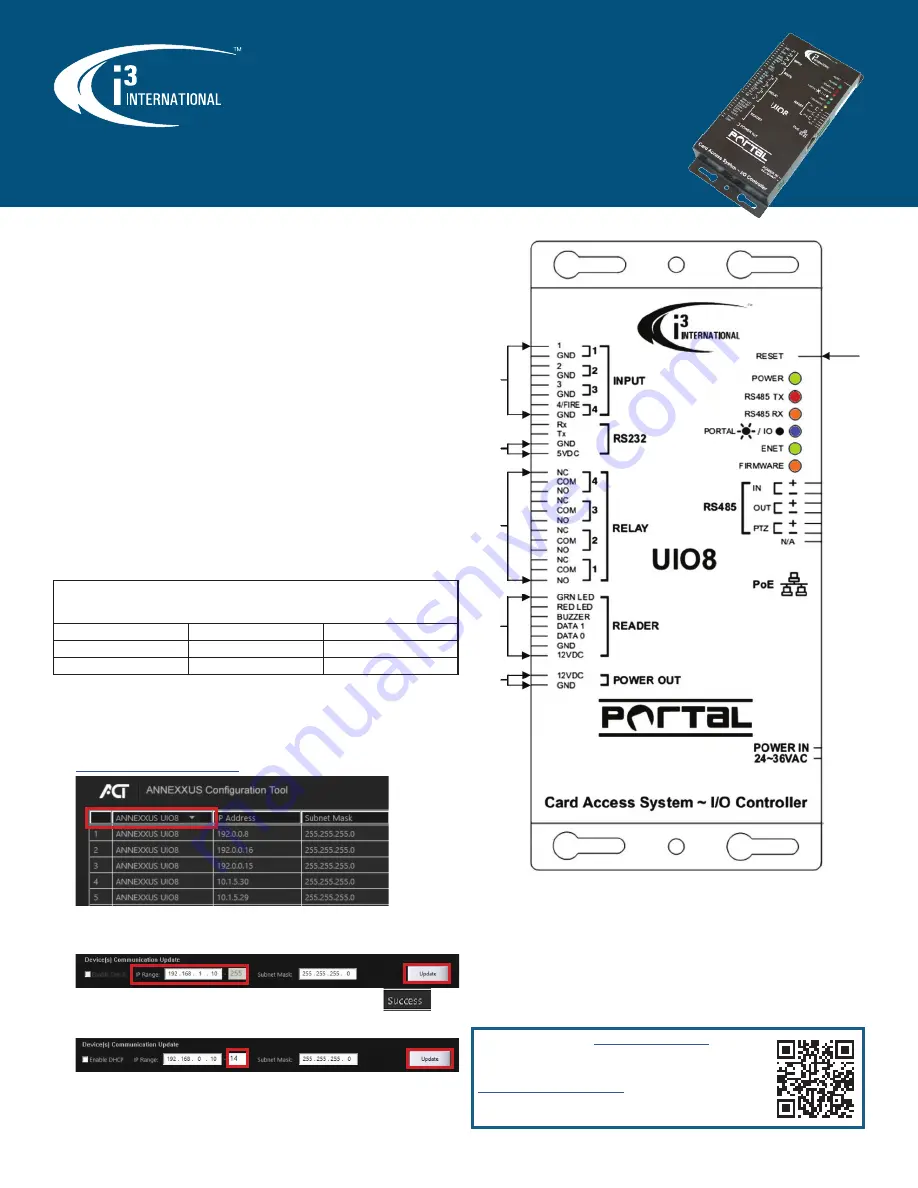
Default Connection Information
Reset
Device
Sensor Input
5VDC
Control Output
12VDC
Reader (Wiegand)
Wiring Diagram
Changing IP Address in ACT
UIO8 devices cannot share an IP address, each UIO8 requires its own unique IP address.
1.
Connect your UIO8 device to the Gigabit switch.
2.
On your i3 NVR, launch i3 Annexxus Configuration Tool (ACT) v.1.5 or higher.
You can download and install the latest ACT installation package from i3 website:
https://i3international.com/download
LED Status
A control joystick, LCD, and keys are on the front panel of the control keyboard. The LCD
displays system status and operation information and the joystick controls the panel for
4-directional (Up, Down, Left, and Right) speed movement and manual positioning.
•
Power LED (Green LED): indicates power connection to the board
•
RS485 TX-RX: indicates signal transmission to and from connected devices
•
Portal / IO (Blue LED): indicates current function of the UIO8 board.
Blue LED On - Portal Card Access; Blue LED Off - IO Control
•
ENET (Green LED): blinking LED indicates the health of the UIO8 device
•
Firmware (Orange LED): blinking LED indicates firmware upgrade in progress.
UIO8 default IP address is
192.0.0.10
UIO8 default subnet mask address is
255.255.255.0
Default UIO8 Control Port:
230
. Default HTTP Port:
80
.
Firmware Version
Default Login
Default Password
v.2.3.2, and below
i3international
uio8
v.2.3.3, or higher
i3admin
i3admin
3.
Select “ANNEXXUS UIO8” in the model drop-down menu to show only the UIO8
devices in the list.
4.
Enter the new
IP address
and
Subnet Mask
of the camera in the Device(s)
Communication Update area.
5.
Click
Update
and then
Yes
in the confirmation window.
Tip:
New IP address must match the IP range of LAN or NVR’s NIC1.
6.
Wait a few moments for a “
Success
” message in the Result field.
Repeat Steps 1-5 for all detected UIO8 devices OR
7.
Assign IP range to multiple cameras by selecting two or more UIO8 in ACT, then
entering the starting IP address and the final IP octet for your IP range.
Click
Update
and then
Yes
in the confirmation window.
Wait until “
Success
” message is shown for all selected UIO8.


