


17
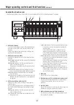
Inside the front cover
①
HDD units [Option]
Only the hard disk drive encased in the dedicated hard
disk drive canister (HDD units) can be installed in the
recorder.
Contact your dealer about purchasing, installing, and
replacing the hard disk drives.
②
HDD status indicator [STS]
Indicates the operational status of the respective hard
disk drive.
Lights green:
Indicates that the power of the (formatted)
hard disk is on.
Blinks green:
Indicates that the respective hard disk
drive is for playback use only.
(Recording is unavailable using the respective hard
disk drive.)
Blinks orange:
Indicates that the respective hard disk
drive is currently being formatted, added or removed.
Blinks red:
Indicates that formatting of the hard disk
drive has failed.
Off:
Indicates that the power of the hard disk drive is off,
Indicates that the hard disk drive is not connected/
recognized.
③
HDD access/failure indicator (A/F)
Indicates the status (access/failure) of the respective
hard disk drive.
When an HDD failure (error) occurs during operation in
the RAID1/RAID5/RAID6 mode, the indicator will light/
blink red.
Blinks green:
Indicates that the respective hard disk
drive is being accessed.
Off:
Indicates that the respective hard disk drive is not
being accessed.
Lights red:
Indicates that the respective hard disk drive
is faulty (which can be recovered by replacing the
hard disk drive)
In the RAID1/RAID5 mode, it indicates that the
respective hard disk drive is the first faulty drive.
In the RAID6 mode, it indicates that the respective
hard disk drives are the first and second faulty drive.
Blinks red:
Indicates that the respective hard disk drive
is faulty (which cannot be recovered even by replac-
ing the hard disk drive)
In the RAID5 mode, it indicates that the respective
hard disk drive is the second faulty drive.
In the RAID6 mode, it indicates that the respective
hard disk drive is the third faulty drive.
Blinks orange:
Indicates the drive in data recovery in
RAID1/RAID5/RAID6 mode (it may appear that the
indicator lights orange when recovery is being pro-
cessed at high speed)
④
HDD slots
Up to 9 HDD units can be installed.
⑤
Maintenance port (For maintenance purpose only)
Use this port to connect directly to a PC and perform
maintenance operations. Do not use for normal
operation.
⑥
Restart switch
Restarts the recorder. Insert a fine stick, like a paper clip
and keep pressing for more than 5 seconds.
⑦
HDD unit holding bracket fixing thread hole
Use this hole to fix the HDD unit holding bracket when
transporting the recorder.
*
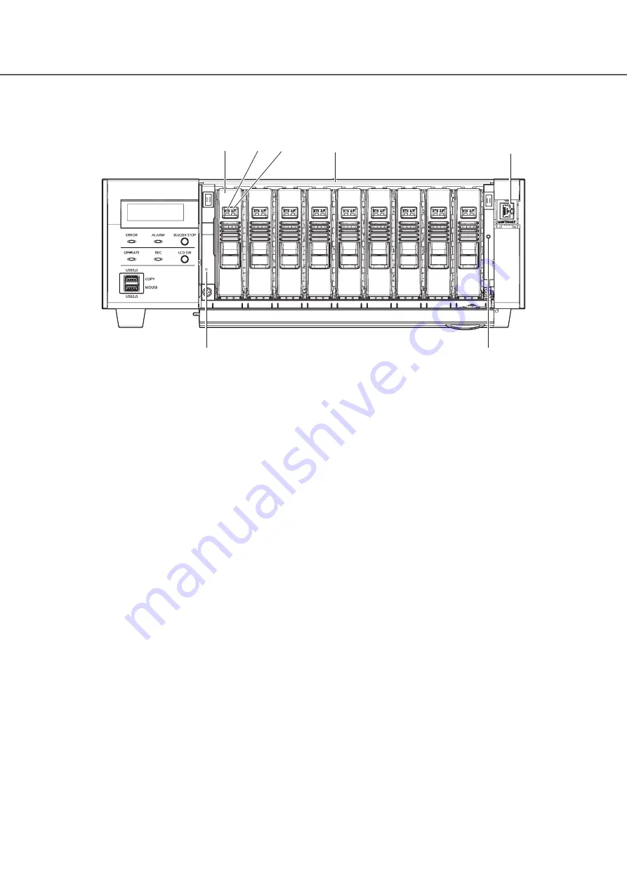
The following illustration shows that 9 HDD units are installed with the "HDD unit holding brackets" removed.
Major operating controls and their functions
(continued)
➀
➁
➂
➃
➄
➆
➅


