
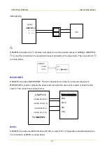


VHF (136-174 MHz)
Troubleshooting Flow Chart
26
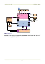
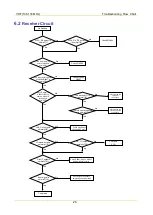
6.2
Receiver Circuit
The second LO is
normal?[6]
No
No
Yes
Yes
Yes
Yes
Yes
Yes
No
No
No
No
No
No Receive
No
Yes
Yes
Check RX
VCO
Yes
No
Yes
No
No
Yes
3V3A_RX output is
normal?[1]
LNA_Out outputs
normally?[8]
Input signal is
normal?[12]
Yes
Completed
No
3V3A_RX_RF output
is normal?[2]
Check Q6004
Check Q6005
Check Q6006,
Q6007
The static working
point of Q6005 is
normal?[3]
The static working point
of Q6006/Q6007 is
normal?[4]
Input IF signal via
U6001PIN47 to
check whether IF
sensitivity is
normal?[5]
18MHz crystal oscillator
is normal?[7]
Check Q6003 and
peripheral
components
Check Q6002 and
other appropriate
components
LO signal outputs
normally?[9]
First IF outputs
normally?[11]
RX_LO outputs
normally?[10]
Check Z6001, Q6006, Q6007
and peripheral circuits
Check Q6005 and
front-end RF circuit
Check signal frequency,
amplitude and modulation
information
Summary of Contents for PD502
Page 1: ...PORTABLE...
Page 5: ...VHF 136 174 MHz...
Page 13: ...VHF 136 174 MHz Exploded View and Packaging Guide 7 3 2 Packaging Guide...
Page 18: ...VHF 136 174 MHz Circuit Description 12...
Page 43: ...PCB 3 9 PCB VHF 136 174 MHz...
Page 44: ...PCB 3 VHF 136 174 MHz...
Page 71: ...UHF1 400 470 MHz...
Page 79: ...UHF1 400 470MHz Exploded View and Packaging Guide 7 3 2 Packaging Guide...
Page 84: ...UHF1 400 470MHz Circuit Description 12...
Page 108: ...UHF1 400 470MHz PCB 36 9 PCB...
Page 109: ...UHF1 400 470MHz PCB 37...
Page 136: ...1616300000260 2014 03 17 L07157 4...