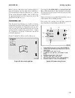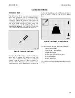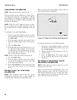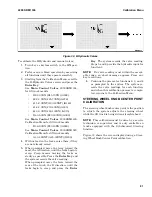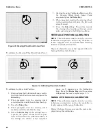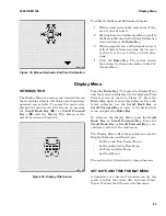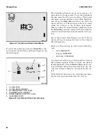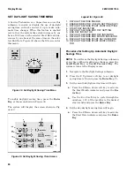
Figure 32. E-Hydraulic Valves
To calibrate the E-Hydraulic and manual valves:
1.
Turn key or keyless switch to the ON posi-
tion.
2.
Perform an air bleed operation by exercising
all functions until they operate smoothly.
3.
Starting from the Calibration Menu, scroll to
the E-Hydraulic Valves screen and press the
Enter Key.
See Main Control Valves 2000SRM1334,
for lift truck models
• E2.2-3.5XN (E45-70XN) (A268)
• J2.2-3.5XN (J45-70XN) (A276)
• J1.5-2.0XNT (J30-40XNT) (K160)
• J1.6-2.0XN (J30-40XN) (A935)
• J4.0-5.0XN (J80-100XN) (A970)
• E4.0-5.5XN (E80-120XN) (A099)
See Main Control Valves 2000SRM1439,
Calibration Menu for lift truck models
• E1.6-2.0XN (E30-40XN) (A269)
See Main Control Valves 2000SRM1520,
Calibration Menu for lift truck models
• A1.3-1.5XNT (A25-30XNT) (D203)
4.
With no load on the forks, raise them, if they
are not already raised.
5.
When prompted, move the lever toward the
mast, the A direction, until the forks begin to
creep. Creep means moving the forks as
slowly as possible. Press the Enter Key and
the system records the valve reading.
When prompted, move the lever toward the
rear of the truck, the B direction, until the
forks begin to creep and press the Enter
Key. The system records the valve reading.
Steps 5 and 6 provide the hydraulic input for
function 1.
NOTE:
If a valve reading is not within the accept-
able range, an abort message appears. Press any
key to continue.
6.
Continue the process for functions 2, 3, and 4
as prompted by the system. The system re-
cords the valve readings for each function,
and when this calibration process is comple-
ted, returns to the Calibration Menu.
STEERING WHEEL KNOB CENTER POINT
CALIBRATION
The steering wheel knob center point is the position
to which the system adjusts the steering wheel
while the lift truck is being driven straight ahead.
NOTE:
This calibration must be done by a service
technician or supervisor and is only available on
trucks equipped with the Synchronized Steering
function.
Figure 33 shows the screen display during a Steer-
ing Wheel Knob Center Point calibration.
2200 SRM 1336
Calibration Menu
81
Summary of Contents for A1.3-1.5XNT
Page 6: ... THE QUALITY KEEPERS HYSTER APPROVED PARTS ...
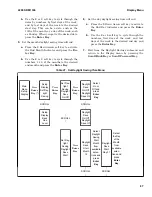
Page 9: ...Figure 3 Technician Flowchart Sheet 1 of 4 2200 SRM 1336 Menu Flowchart 3 ...
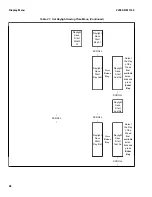
Page 10: ...Figure 3 Technician Flowchart Sheet 2 of 4 Menu Flowchart 2200 SRM 1336 4 ...
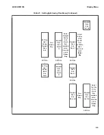
Page 11: ...Figure 3 Technician Flowchart Sheet 3 of 4 2200 SRM 1336 Menu Flowchart 5 ...
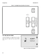
Page 12: ...Figure 3 Technician Flowchart Sheet 4 of 4 Menu Flowchart 2200 SRM 1336 6 ...
Page 123: ......
Page 124: ...TECHNICAL PUBLICATIONS 2200 SRM 1336 2 14 8 13 4 13 12 12 3 12 12 11 ...


