


Operation
6
218
809480
Instruction Manual
XPR300
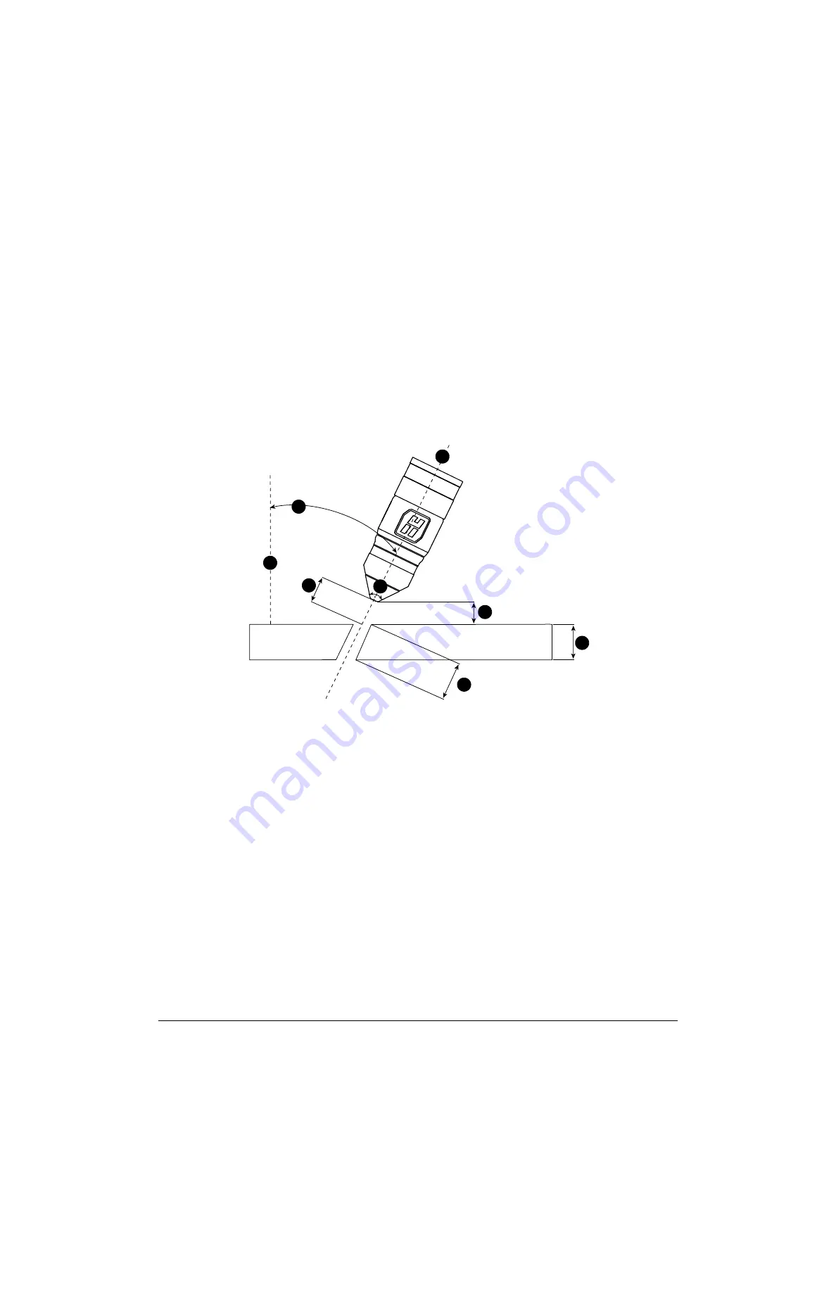
Bevel cutting
During bevel cutting, the torch is at an angle (
not
perpendicular) to the workpiece. The angle of the
torch (relative to the workpiece) has an effect on the bevel cut angle of the metal.
The torch and consumable parts are designed so that the torch position can range from 0° – 52° so
that the torch tip remains the closest point to the workpiece. If you need an angle greater than 52°,
you can raise the torch to increase the clearance.
Figure 58
– Example orientation of a torch during bevel cutting
Arc voltage settings for bevel cutting depend on the torch position, metal
thickness, cut speed, and effective cut height. For this reason, cut charts
only include arc voltages for perpendicular-position cutting.
90°
8
1
2
3
4
6
5
7
1
Perpendicular line
: The imaginary line that is
perpendicular (at a 90° angle) to the workpiece.
2
Bevel angle
: The angle between the center line of
the torch and an imaginary line that is
perpendicular to the workpiece.
3
Cut height
: The linear distance from the center of
the torch to the workpiece surface along the torch
center-line. For optimal results, select a cut height
that is based on an “effective thickness” value in
the cut charts.
If a specific cut height is inconsistent with a
clearance requirement, select a slightly higher cut
height to prevent torch collisions.
4
Cone angle
: All XPR torches have a 76° cone
angle that makes it possible to tilt or position the
torch up to 52°. If you need an angle greater than
52°, you can raise the torch to increase the
clearance.
5
Torch center line
: The imaginary line along the
central axis of the torch.
6
Clearance
: The vertical distance from the lowest
point of the torch to the surface of the workpiece.
Make sure that the distance is at least
2 mm – 3 mm (0.080 in. – 0.120 in.) to minimize
torch contact with any slag on top of the plate.
7
Nominal thickness
: The vertical thickness of a
workpiece. This is the thickness of the metal that
the plasma arc cuts, marks, or pierces.
8
Effective thickness
: The distance that the plasma
arc travels through the metal while cutting. This
value is equal to the nominal thickness, divided by
the cosine of the bevel angle.
Summary of Contents for XPR170
Page 1: ...XPR300 Instruction Manual 809480 REVISION 6 ENGLISH ...
Page 8: ......
Page 38: ...Specifications 1 38 809480 Instruction Manual XPR300 ...
Page 72: ...Qualifications and Requirements 2 72 809480 Instruction Manual XPR300 ...
Page 146: ...Installation 3 146 809480 Instruction Manual XPR300 ...
Page 202: ...Coolant Installation 5 202 809480 Instruction Manual XPR300 ...
Page 236: ...Operation 6 236 809480 Instruction Manual XPR300 ...
Page 360: ...Diagnostics and Troubleshooting 8 360 809480 Instruction Manual XPR300 ...
Page 406: ...Parts List 9 406 809480 Instruction Manual XPR300 ...
Page 417: ...417 Overview Sheet 1 of 22 013403 013403 ...
Page 418: ...418 Plasma power supply 1 Sheet 2 of 22 013403 ...
Page 419: ...419 Plasma power supply 2 Sheet 3 of 22 013403 ...
Page 420: ...420 Plasma power supply 3 Sheet 4 of 22 013403 ...
Page 421: ...421 Plasma power supply 4 Sheet 5 of 22 013403 ...
Page 422: ...422 Plasma power supply 5 Sheet 6 of 22 013403 ...
Page 423: ...423 Plasma power supply 6 Sheet 7 of 22 013403 ...
Page 424: ...424 Plasma power supply 7 Sheet 8 of 22 013403 ...
Page 425: ...425 Gas connect console 1 Sheet 9 of 22 013403 ...
Page 426: ...426 Gas connect console 2 Sheet 10 of 22 013403 ...
Page 427: ...427 Torch connect console Sheet 11 of 22 013403 ...
Page 428: ...428 Coolant system Sheet 12 of 22 013408 ...
Page 429: ...429 Gas system 1 Sheet 13 of 22 013403 ...
Page 430: ...430 Gas system 2 Sheet 14 of 22 013403 ...
Page 431: ...431 Gas system 3 Sheet 15 of 22 013403 ...
Page 438: ...438 Wireless subsystem block diagram Sheet 22 of 22 013403 ...


