


SYSTEM CONFIGURATION
940043-002
INTEGRATED ENTERPRISE NETWORK
5-7
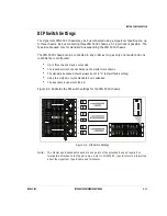
DIP Switch Settings
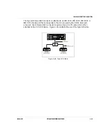
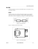
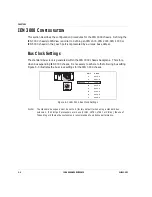
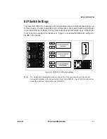
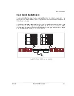
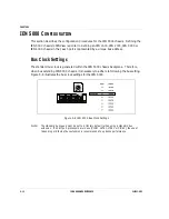
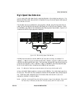
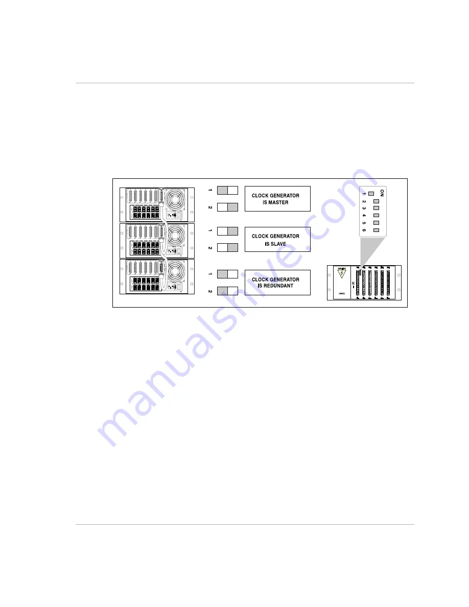
The Hypercom IEN 3000 chassis may be bus connected using a Hypercom Type B cable, up
to three chassis. In a two chassis IEN 3000 configuration, one chassis must be set to Master
Clock (default factory settings), and the other must be set to Redundant Clock. If the Master
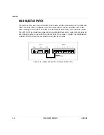
Clock fails, the redundant clock takes over. Figure 5-4 illustrates the DIP switch settings for
the IEN 3000 chassis.
Figure 5-4 IEN 3000 DIP Switch Settings
Note:
The Master and Redundant chassis are end points of the expanded bus and require bus
terminators attached to the Type B cables. Refer to CHAPTER 4, Type B for more information
about the Hypercom Type B cable and terminator.
Summary of Contents for IEN 1000
Page 4: ......
Page 10: ...TABLE OF CONTENTS VI IEN HARDWARE REFERENCE 940043 002 ...
Page 11: ...C H A P T E R 1 Introduction In This Chapter IEN Hardware Reference 1 3 ...
Page 12: ......
Page 14: ...CHAPTER 1 1 4 IEN HARDWARE REFERENCE 940043 002 ...
Page 16: ......
Page 48: ......
Page 108: ...CHAPTER 3 3 62 IEN HARDWARE REFERENCE 940043 002 ...
Page 110: ......
Page 164: ...CHAPTER 4 4 56 IEN HARDWARE REFERENCE 940043 002 ...
Page 166: ......
Page 180: ...CHAPTER 5 5 16 IEN HARDWARE REFERENCE 940043 002 ...
Page 181: ...C H A P T E R 6 System Configuration In This Chapter IEN 1000 Configuration 6 3 ...
Page 182: ......
Page 190: ...CHAPTER 6 6 10 IEN HARDWARE REFERENCE 940043 002 ...
Page 196: ......
Page 197: ......
Page 198: ...Printed in the United States P N 940043 002 Network Systems ...