


62 Hydro-View User Guide HD0531 Rev 2.0.0
Figure 53: Averaging Configuration
7.5
Edit Points Graph Screen
5
6
9
1
7
8
3
4
2
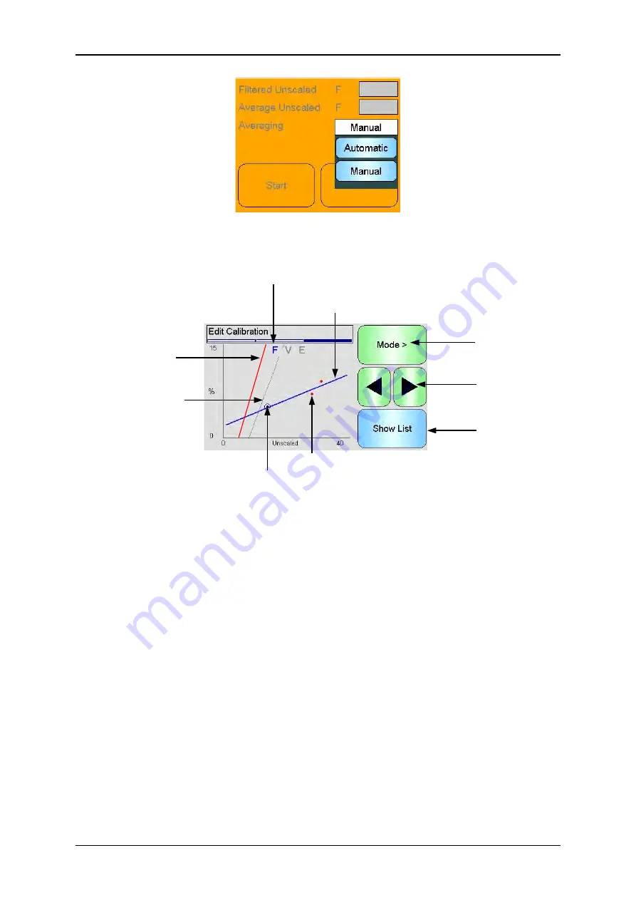
Figure 54: Edit Calibration Points Graph Screen
1. The ‘best fit’ line calculated from the currently included data points.
2. The Calibration limit lines are shown in red if Quick Start Rules are enabled.
3. A point that is further from the ‘best fit’ line than the Tolerance allows is indicated in
red.
4. The point currently highlighted in the list is indicated by a circle.
5. The calibration line currently in the sensor is shown in grey.
6. Show List - Returns to the List view of the points.
7. Left and Right scroll buttons move the point selection up and down the graph. This
enables an out of tolerance point to be identified in the list view. When returning to the
List view, the selected point is highlighted in the list.
8. Change the Measurement Mode calibration displayed on the graph
9. Current Measurement Mode displayed on the graph
Summary of Contents for HV04
Page 4: ...4 Hydro View User Guide HD0531 Rev 2 0 0 ...
Page 6: ...6 Hydro View User Guide HD0531 Rev 2 0 0 ...
Page 12: ...12 Hydro View User Guide HD0531 Rev 2 0 0 ...
Page 14: ...14 Hydro View User Guide HD0531 Rev 2 0 0 ...
Page 22: ...Mechanical Installation Chapter 2 22 Hydro View User Guide HD0531 Rev 2 0 0 ...
Page 28: ...Electrical Installation Chapter 3 28 Hydro View User Guide HD0531 Rev 2 0 0 ...
Page 78: ...Material Calibration Chapter 6 78 Hydro View User Guide HD0531 Rev 2 0 0 ...
Page 80: ...Default PIN Codes Appendix A 80 Hydro View User Guide HD0531 Rev 2 0 0 ...
Page 82: ...USB Memory Stick file format Appendix B 82 Hydro View User Guide HD0531 Rev 2 0 0 ...
Page 84: ...Quick Start Rules Appendix C 84 Hydro View User Guide HD0531 Rev 2 0 0 ...
Page 86: ...Frequently Asked Questions Appendix D 86 Hydro View User Guide HD0531 Rev 2 0 0 ...
Page 92: ...Document Cross Reference Appendix G 92 Hydro View User Guide HD0531 Rev 2 0 0 ...


