background image

Hydro-Logic

®


Flexi Logger 300Ex


User Manual 


22 August 2018 


Page 25 of 74 

Wiring conventions 

Choose the desired combination of sensors in the first column, then wire the 
sensors according to the row across from it.   

For example, for 

1 float switch and 1 HART

 sensor, the float switch (FS) should 

be connected to S1 using pins G and 1.  The HART sensor should be wired to 
S2, with the positive connection on pin 2 and the negative on pin G.  It should be 
assigned address 2. 


Desired 

combination

S1-G

S1-1

S1-2

S1-3

S2-G

S2-1

S2-2

S2-3

S3-G

S3-1

S3-2

S3-3

1

 float switch

FS1

FS1

float switches

FS1

FS1

FS2

FS2

float switches

FS1

FS1

FS2

FS2

FS3

FS3

S1-G

S1-1

S1-2

S1-3

S2-G

S2-1

S2-2

S2-3

S3-G

S3-1

S3-2

S3-3

HART

HART 

addr 2 -

HART 

addr 2 + 

float switch,

 1 

HART

FS1

FS1

HART 

addr 2 -

HART 

addr 2 + 

float switches, 

HART

FS1

FS1

HART 

addr 2 -

HART 

addr 2 + 

FS3

FS3

1

 float switch,

 2 

HART

HART 

addr 1 -

HART 

addr 1 +

HART 

addr 2 -

HART 

addr 2 + 

FS3

FS3

HART

HART 

addr 1 -

HART 

addr 1 +

HART 

addr 2 -

HART 

addr 2 + 

HART 

addr 3 -

HART 

addr 3+

S1-G

S1-1

S1-2

S1-3

S2-G

S2-1

S2-2

S2-3

S3-G

S3-1

S3-2

S3-3

4-20 mA

4-20 mA -

4-20 mA +

float switch,

 1 

4-20 mA

FS1

FS1

4-20 mA -

4-20 mA +

float switches, 

4-20 mA

FS1

FS1

4-20 mA -

4-20 mA +

FS3

FS3

Preferred wiring - sensor connector and pins

Summary of Contents for Hydro-Logic Flexi Logger 300Ex

Page 1: ...www hydro int com LoggerSupport Hydro Logic Flexi Logger 300Ex User Manual ...

Page 2: ...8 Hazardous Area installations 8 Conditions of safe use 9 Sensors permissible values 10 Declaration of Conformity 11 Certification markings 11 Specification 12 Sensor inputs 12 Sensor power supply 12 Data storage 12 Communications 12 Power 12 Mechanical 13 Getting started 14 Powering the logger 14 Connecting to Timeview 15 Recording test data from the sensor 16 Hardware configuration and installat...

Page 3: ...ry packs 32 Storing the logger 32 Changing the battery 33 Lithium battery regulations 34 Configuration with Harvest Software 35 Harvest overview 35 Connecting the device 35 Resetting the logger clock with Harvest 38 Basic configuration 39 Logger Group and Tag 39 Configuring sensors 40 Sensor zero and full scale 41 Recording interval 42 Water level with respect to datum 43 Setting the HART sensor a...

Page 4: ... your data on Timeview 55 Resetting logger clock with Timeview 56 Alarms 57 Logger alarm configuration 57 Set point and alarm condition 57 Hysteresis 58 Timeview alarm configuration 58 Groups and recipients 59 Message contents 59 Alarm routing 60 End to end testing 61 Viewing alarms on plots 62 Battery life 63 Estimating battery life 63 Maximizing battery life 64 Appendix 1 IECEx Certification 65 ...

Page 5: ...explosive atmospheres classified Zone 0 hazard continuously present The Flexi Logger 300Ex is certified to the ATEX and IECEx standards for instrumentation used in potentially explosive atmospheres The Hydro Logic Flexi Logger 300Ex is powered by a lithium battery pack which under normal operating conditions will provide years of operation between replacements dependent on unit configuration Main ...

Page 6: ...ew and accessory sales and our pre wiring and sensor configuration service contact enquiries hydro int com Hydro International welcomes feedback that would improve products or the information presented in this manual Hydro International is continually improving its products and reserves the right to change product specifications without notice Warranty The warranty terms for this product can be fo...

Page 7: ...tery disposal Information related to correct disposal of batteries Revisions 1 2 22 Aug 2017 T Campbell Revision header added Product name changed to Flexi Logger 300Ex Draft for SIRA certificates not yet updated 1 3 13 Sep 2017 T Campbell ATEX certificates updated 1 4 22 Sep 2017 T Campbell Sensor connection info added 1 5 5 Dec 2017 T Campbell HART sensor failure alarm and measurement interval i...

Page 8: ...equirements It is the customer s responsibility to ensure that certification on the Flexi Logger 300Ex and sensors meets the applicable regulatory requirements System certification The Hydro Logic Flexi Logger 300Ex is certified for use only with approved sensors batteries communication cables Connection of any non approved components could result in unsafe operation and will immediately void the ...

Page 9: ...to this port must be approved as SELV or Class 2 equipment against UL 60950 1 UL 6101 1 or an equivalent IEC standard The maximum voltage from a data transfer device shall not exceed 19 7Vdc The Hydro Logic Flexi Logger 300Ex is normally used in damp environments and is unlikely to be placed in a position where an electrostatic build up can take place Under certain extreme circumstances the non me...

Page 10: ...ensor meets the following criteria The sensor must have ATEX or IECEx certification for use in the hazardous zone they are being used in The sensors output parameters are not greater than the maximum permissible values detailed below Parameter Sensor connector permissible values Voltage Out Uo 22 7v Current Out Io 297mA at 14 6v Power Out Po 1 1W Capacitance Ci 0 2uF Inductance Li 1 61mH Combined ...

Page 11: ... Year Year of manufacture IECEx SIR 16 0086X IECEx certification number Sira 16ATEX2252X ATEX certification number Ex ia IIB T4 Ga Protection concept gas group and temperature class Ex ia Intrinsic Safety Certification Zones 0 1 2 IIB Intended for use in an explosive gas atmosphere Ethylene T4 Temperature Class max surface temp 135 C Ga EPL protection relationship Zone 0 TA 20 C to 40 C Ambient te...

Page 12: ...off mode for float switch 10K internal pull up Sensor power supply Power output Pin 3 Switched 18V 250 Ohm series resistance 62mA fuse factory replaceable ATEX requirement Configurable warm up Data storage Storage capacity 29768 16 bit readings total for up to 8 channels Storage intervals 10s 30s 1m 2m 5m 10m 15m 30m 1h 2h 3h 4h 6h 8h 12h Storage interval for each channel can be set independently ...

Page 13: ...04 with connectors Construction Polycarbonate enclosure O ring seals on all external mating surfaces Stainless steel bracket for wall mounting Protection Notes IP68 will withstand 1 2m immersion for 48 hours without significant ingress 1 All connectors must be mated or have sealing caps fitted 2 data communications may not function when immersed 3 gauge pressure based level sensors are not accurat...

Page 14: ...nfiguration service The instructions cover the most important aspects of logger operation They should be carried out before the logger is installed on site Powering the logger The logger is shipped in the OFF state To power it you must open the enclosure and plug in the HLC module Once you do this you should see a green flash on the LED The logger is now ON You should see a blue LED flash every tw...

Page 15: ...on the LED The dial out can also be triggered with a strong magnet near the reed switch 2 without the case being opened The enclosure should never be opened in the Hazardous Area The logger will then begin a series of steps to call out to Timeview Progress can be followed using the Status LED flash patterns or you can just wait for a few minutes until the red blue and green flashing has stopped an...

Page 16: ...lock is reset either by Resetting logger clock with Timeview or Resetting the logger clock with Harvest This will clean any blank data points that were recorded with no sensor connected and ensure that data points from the sensor are correctly time stamped Now leave the logger to record some data The logger will be configured to take measurements every 5 or 15 minutes so leave it for half an hour ...

Page 17: ...on system via either an internal and or external antenna The modem includes a standard SIM interface The orange lines show the power distribution There is an internal battery which can typically provide years of operation The HLC is a small module containing a rechargeable battery which provides boost power for the modem and sensor as required Yellow zones in the diagram are ATEX components or sub...

Page 18: ...ves are held together using six captive screws Sealing of the enclosure halves is via O ring seals which include the body seal and screw seals It is imperative that all the seals are in place in good condition and clean to maintain the IP68 sealing On the underside of the enclosure are three sensor connectors S1 to S3 wired in parallel serial port for local communication LC and external antenna co...

Page 19: ...racket The Flexi Logger 300Ex is supplied with a wall mounting bracket as standard See below for hole spacing diameter and clearance Inside the Enclosure Inside the enclosure the circuit board has a SIM holder 1 dial out button and LED 2 internal antenna 3 HLC module 4 and battery pack 5 ...

Page 20: ... Patch The breather patch on the underside of unit allows pressure transducers connected to the unit to vent to atmosphere If the GORE protective patch is damaged it should be replaced otherwise water could enter the pressure transducer vent tube and permanently damaging the sensor ...

Page 21: ... Purple flashes internal external antenna selection Irregular green logger sending commands to modem not data Blue red regular modem on but no signal or unable to register Double blue regular modem on and registered with network Blue red blue regular alarm present but not registered on network Triple blue regular alarm present registered on network dialling out Solid blue comms active waiting to r...

Page 22: ...hat have ATEX IECEx certification and conform to the input output parameters detailed on the certificate should be used on the Flexi Logger 300Ex logger in a Hazardous Area See Sensors Permissible Values HART sensors Up to three HART sensors can be connected They must be addressed and wired as shown in Wiring conventions The address should be set with a HART modem before installation using the man...

Page 23: ...me as for HART sensors 4 20mA sensors cannot be mixed with HART sensor since the loop current is shared and will not be accurate Connecting a 4 20mA sensor will prevent use of digital input 2 on the other sensor connectors since this pin is used as the sensor positive loop connection The sensor is powered for a user specified warm up period 1 before a measurement is taken Long warm up periods will...

Page 24: ...r 300Ex Each float switch should be wired and connected as shown in Wiring conventions The logger records the time that the switch closes and opens The resolution of the switch time is based on the interval selected for the channel Sensor power should be disabled for normal volt free sensors If you have a powered level sensor contact Support website ...

Page 25: ... S3 G S3 1 S3 2 S3 3 1 float switch FS1 FS1 2 float switches FS1 FS1 FS2 FS2 3 float switches FS1 FS1 FS2 FS2 FS3 FS3 S1 G S1 1 S1 2 S1 3 S2 G S2 1 S2 2 S2 3 S3 G S3 1 S3 2 S3 3 1 HART HART addr 2 HART addr 2 1 float switch 1 HART FS1 FS1 HART addr 2 HART addr 2 2 float switches 1 HART FS1 FS1 HART addr 2 HART addr 2 FS3 FS3 1 float switch 2 HART HART addr 1 HART addr 1 HART addr 2 HART addr 2 FS3...

Page 26: ...ng diagrams for most compatible sensors can be found in Harvest Software when configuring the logger Fitting the sensor plug Strip back 30 mm of outer insulation including any foil or braided screen Assemble the cable and plug components as illustrated above before wiring the sensor Wire the sensor to the plug according to the sensor type Tighten the threads between parts A B before tightening the...

Page 27: ...to pass from the sensor vent tube through both mating connectors and out through the GORE membrane There is no need to drill the sensor connectors When installing trim the vent tube and unused conductors to about 10mm beyond the end of the outer insulation Do not crush the end of the vent tube Approved sensors Hydro International have a list of approved sensors which can be supplied with the Hydro...

Page 28: ...ic Flexi Logger 300 has an internal antenna which under normal conditions is the best choice There is also a connector for an external antenna which can be used in more challenging signal conditions The external antenna must be mounted outside of all enclosures in a protected position above ground Examples of conditions that may require an external antenna Installing the logger in a metal enclosur...

Page 29: ...nnector Do not locate the antenna beside metalwork or cables it needs to be in the open or surface mounted depending on the antenna type Avoid areas where the antenna may be overgrown with vegetation The external antenna connector is fitted with a sealing cap to protect the connector when not in use If an external antenna is not used the cap must be fitted to protect the antenna connector Other ty...

Page 30: ... pre installed Using your own SIM Many clients successfully use their own SIMs with the Hydro Logic Flexi Logger 300Ex Both Private APN and fixed IP SIMs can be used You can still use Timeview with your own SIM but you must purchase an Own SIM Timeview package The following points are important if you are using your own SIM The SIM must be data enabled Roaming SIMs are recommended A contract SIM i...

Page 31: ...so will stay in the bottom half of the enclosure when undone 2 Carefully remove the lid of enclosure insuring that the seals are not lost 3 Slide the SIM into the SIM carrier top right of the board observing the correct orientation of the corner cut out in the SIM The SIM holder is a push push type Push the SIM in once it clicks into place Push it again to release The SIM must be correctly oriente...

Page 32: ...ified for use with the Flexi Logger 300Ex via ATEX IECEx Hazardous Area certification The use of any other non approved batteries will void the ATEX IECEx product certification Replacement batteries can only be obtained from Hydro International and approved distributors see Sales enquiries Storing the logger Store the Hydro Logic Flexi Logger 300Ex with the HLC module removed It does not matter if...

Page 33: ... in the bottom half of the enclosure when undone 2 Carefully remove the lid of enclosure ensuring that the seals are not lost 3 Unplug the HLC module and place it to one side 4 Unplug the battery wire and lift the battery out Fit the new battery 5 Replace the HLC module 6 Refit the enclosure top making sure that the 7 O ring seals 6 small one large are in place and not contaminated with dirt or ot...

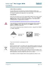
Page 34: ...gulations pdf These batteries are classified as Class 9 Dangerous Goods and are subject to regulations UN3090 Lithium Metal Batteries and UN3091 Lithium Metal Batteries Contained in Equipment They must be packaged securely and labelled as shown along with the UN3090 or UN3091 designation They must not be taken on passenger aircraft Disposal Disposal should be done in accordance with the applicable...

Page 35: ...vest on your PC you should install the newest version Harvest supports older logger versions but new loggers will not work with old versions of Harvest Connecting the device To read or configure the Hydro Logic Flexi Logger 300Ex locally with a Windows PC you will need a copy of Harvest software and a serial communications cables part no PDA1100 3435 The serial communications port on the Flexi Log...

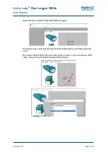
Page 36: ...6 of 74 Start Harvest and select Start Wizard Read logger Press Next twice selecting the default options Data Since Last Download and Local Now select the COM port that the serial cable is using If you are using a USB cable choose the port labelled Isodaq USB Modem ...

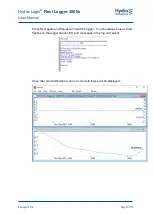
Page 37: ... 22 August 2018 Page 37 of 74 Press Next again and Harvest will read the logger You should see blue and red flashes on the logger status LED and messages in the log on Harvest Once the command finishes one or more data traces will be displayed ...

Page 38: ...lect Configure to access the logger configuration The logger configuration box has tabs which relate to different parts of the logger configuration For now ignore them and hit Next 3 times The configuration from the PC will now be sent to the logger Although you have not changed anything the new configuration will reset the logger clock and clear any time series data that was stored in the logger ...

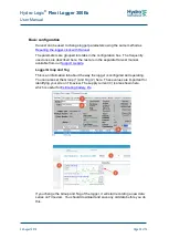
Page 39: ...re in the separate Harvest manual available from our Support website Logger Group and Tag This is an information tab about the way the logger is configured and operating You can also set the Group 1 and Tag 2 here These values are important for identifying your site on Timeview The supply current 3 is also shown here which is useful for Estimating battery life If you change the Group and Tag of th...

Page 40: ...nfigured for your sensor and you can skip this part These tabs are used for sensor configuration Press the Change Sensor tick box 1 to access the list of applicable sensors for this channel The drop down list shows sensors applicable to this channel Once the sensor is selected you can configure it further depending on the sensor type See the section on Sensors for specific instructions ...

Page 41: ...le values for conversion to engineering units must be specified in Harvest and they should match those in the sensor itself The warm up time should be set for long enough to allow the sensor to power up and get a stable reading This varies for different sensor Long warm up times should be avoided since they waste battery power ...

Page 42: ...ugust 2018 Page 42 of 74 Recording interval You can change how often measurements are taken and stored by changing the Interval parameter 1 If you select intervals below 5m you will shorten the battery life of the logger 5m or 15m are used typically ...

Page 43: ...ermine the sensor depth and apply the datum offset during configuration In the example above the water is 2 2m deep with respect to arbitrary datum D The sensor is only d 1 2m deep in the water but when the level is set the offset to the datum is automatically applied so the logger displays levels with respect to the datum here 2 2m This method works for both HART and 4 20mA water level sensors Th...

Page 44: ...an set the HART address using the logger and a PC with a serial terminal program there is no need for a separate HART modem If required To set the HART address Connect the Hydro Logic Flexi Logger 300Ex to your PC with a serial cable Connect ONLY the sensor you wish to set the address of to any sensor connector on the logger Ensure that the logger is configured for at least one HART sensor Enable ...

Page 45: ... scan all addresses from 0 to 15 Once it discovers a sensor it will set the address of that sensor to the desired address and stop scanning You can also set the address as 0 if you want the sensor to be used for normal 4 20mA output Non zero addresses will produce ad fixed loop current typically 12mA You can now remove the sensor and set the addresses of more or leave it connected and configure th...

Page 46: ... in logger firmware version 1 74 or DNP3 version 21 74 They are configured by setting the number of consecutive failures which will trigger an alarm in the System Alarms tab A sensor failure is non response to at HART polling command The failure total is cleared after the first good response In the example on the screen shot an alarm will be produced when the failure total rises above 3 so the 4th...

Page 47: ...be configured with Harvest to scan both antennas and use the best signal To do this enable the tick box as shown below and configure the logger with this setting Do not enable the external antenna if one is not fitted the logger will try to use it and reduce the battery life Sending data to a server Timeview Do not change the parameters here unless you are using your own telemetry server The ones ...

Page 48: ...gic Flexi Logger 300Ex User Manual 22 August 2018 Page 48 of 74 Other systems Hydro Logic Flexi Loggers support many SCADA systems that use the DNP3 protocol Contact Sales enquiries to discuss your requirements ...

Page 49: ...it can do this it can be reconfigured remotely to make other changes so it is very important that the logger is set up to transfer data automatically The logger should have shipped pre configured to do this but you should check before you take it to site On the Check in tab the Daily Check in option is set you must ensure that there is a range of times specified for the logger to check in to Timev...

Page 50: ...ption and reduce battery life It also increases the amount of data transfer so you need to have an Hourly data package enabled on Timeview if you are using a SIM supplied by Hydro International Contact Sales enquiries to arrange this Note that the logger will check in every 3 hours AND daily within the times specified on the Check in Window If you don t want the daily check in the window values sh...

Page 51: ...SIM you will need to change the parameters 1 so they match those required by the SIM provider See SIM cards You should set the local time zone 2 so that times are displayed with your correct local time on Timeview Note that Daylight Savings or Summer time is not used by these loggers They always display in local standard time ...

Page 52: ...verage supply current and reduce battery life You can also do External antenna configuration here 2 The Show on Map 3 button will display a browser page with location of the mast used for mobile data transmission not the location of the logger it may be a few km away This feature requires an internet connection on your PC and depends on a third party website which may change over time ...

Page 53: ...ing logger firmware select the correct Logger Type If you select Identify Device Before Upgrade Harvest will automatically check that the device is of the correct type and if the firmware upgrade is necessary If you select Restore Configuration After Upgrade the logger will be read before the upgrade and reconfigured after the upgrade automatically re synchronizing the logger clock Normally both t...

Page 54: ... Further information is available in the Timeview Advanced User Manual which can be downloaded from the Support website Timeview overview Timeview is a website hosted by Hydro International where data from the Hydro Logic Flexi Logger can be displayed and downloaded This way you can monitor your site assets remotely from your desktop The website address is http timeview2 net ...

Page 55: ...ide of the page Enter the serial number from the logger cap or from the delivery note or box label Either is fine Then press Search Your logger serial number should now appear in the Logger Profiles page Press View You should now see a page showing data from the logger There will be no data there because there is no sensor connected The logger has been off so the clock will not be accurate Both fa...

Page 56: ...e that this is always Standard Time Daylight Saving or Summer Time is not displayed on Timeview Resetting logger clock with Timeview You can clear the clock error message and set the logger clock accurately using Timeview Do this by selecting Configuration Then select Reset Logger Clock and confirm you want to do this The next time the logger calls in the clock will be reset ...

Page 57: ... Alarm information from site is then forwarded from Timeview to individuals or groups Harvest software is used for configuring alarms There is also some setup required on Timeview Both the logger and Timeview configuration must be correct for alarms to work properly Logger alarm configuration The Alarms check box 1 is on the sensor tab Once selected you get the alarm config box Set point and alarm...

Page 58: ... degrees before the logger checks in with a return to normal event The Alpha field can be used to provide some noise reduction in special circumstances but should normally be left as 0 Timeview alarm configuration Provided the logger is transferring data to Timeview correctly there is no more alarm setup required on the logger Once you have configured alarms on the logger trigger a dial out to Tim...

Page 59: ...her email addresses or SMS mobile numbers You can add many recipients to each group Note that SMS messages are charged and you must have credits for them on your Timeview account Contact Sales enquiries to arrange this Message contents The alarm call from the logger contains the channel number set point and direction of the alarm set or return to normal It does not contain descriptive information ...

Page 60: ... data on Timeview and select Configuration 1 On the Alarm routing page 1 you can see the alarm set point you configured on the logger 2 Use the drop down selections to choose the channel set point group and message then created the alarm with the green symbol The alarm should now appear in the list Now you need to test it ...

Page 61: ...he LED on the logger will start flashing blue rapidly as the modem is switched on This will start very shortly after a measurement is taken and for 5m recording this happens on the cardinal points of time look at your PC clock for times like 10 05 10 10 etc assuming you used this PC configure and reset the logger Once the logger has stopped flashing you should receive the alarm email or SMS messag...

Page 62: ...his case The logger will dial out again to report the return to normal event Viewing alarms on plots The Graph Dynamic is the best way to view alarms on plots You may need to refresh the page to see recent alarms use ctrl refresh to force a page update Alarms are shown as red circles on plots while return to normal events are green The set point is a red line and the hysteresis band is grey ...

Page 63: ...predict issues Double click on a plot on Harvest to display the logger configuration If you hover over the Internal label text will show you a conservative battery life estimate 2 Here the average current consumption 1 is 3 3mA For a 96 Ah Lithium battery the life estimate is 3 3 years You can easily do this calculation on a browser The average current consumption is often high for a few days afte...

Page 64: ...ted while daily calls show that the system is still in correct operation Avoid low signal strength areas modem signal on Harvest 10 Fit an external antenna if necessary to improve the signal but don t use one if the internal antenna works well Use a 5m or 15m storage interval for all channels Shorter intervals will use significantly more power Avoid sensors that require long warm up times or have ...

Page 65: ...Hydro Logic Flexi Logger 300Ex User Manual 22 August 2018 Page 65 of 74 Appendix 1 IECEx Certification ...

Page 66: ...Hydro Logic Flexi Logger 300Ex User Manual 22 August 2018 Page 66 of 74 ...

Page 67: ...Hydro Logic Flexi Logger 300Ex User Manual 22 August 2018 Page 67 of 74 ...

Page 68: ...Hydro Logic Flexi Logger 300Ex User Manual 22 August 2018 Page 68 of 74 ...

Page 69: ...Hydro Logic Flexi Logger 300Ex User Manual 22 August 2018 Page 69 of 74 ...

Page 70: ...Hydro Logic Flexi Logger 300Ex User Manual 22 August 2018 Page 70 of 74 Appendix 2 ATEX Certificate ...

Page 71: ...Hydro Logic Flexi Logger 300Ex User Manual 22 August 2018 Page 71 of 74 ...

Page 72: ...Hydro Logic Flexi Logger 300Ex User Manual 22 August 2018 Page 72 of 74 ...

Page 73: ...he relevant Union harmonisation legislation ATEX Directive 2014 34 EU Radio Equipment Directive RED 2014 53 EU Restrictions of Hazardous Substances RoHS Directive 2011 65 EU 6 References to the relevant harmonised standards used including the date of the standard or references to the other technical specifications including the date of the specification in relation to which conformity is declared ...

Page 74: ...r 0518 Certificate numbers IECEx SIR 16 0086X SIRA 16ATEX2252X Production quality assurance notification QAN SIRA 16ATEXM742 Ex Coding Ex ia IIB T4 Ga Signed for and on behalf of Hydro International Unit 3 Scion House Innovation Park Stirling FK9 4NF Tim Campbell Design Engineer 11 April 2018 ...

Reviews: