background image


M

at

 –Nr.

 669648 /

 S

tand:

 19.

09.

20

18 D /

 E

 / F


Bedienungsanleitung 

(Originalanleitung) 

User Manual 

(Translation of original 

instruction) 

Notice d’utilisation 

(Traduction de l’original) 


Elektronischer 
Druckschalter 

Electronic 
Pressure Switch 

Manocontacteur 
électronique 
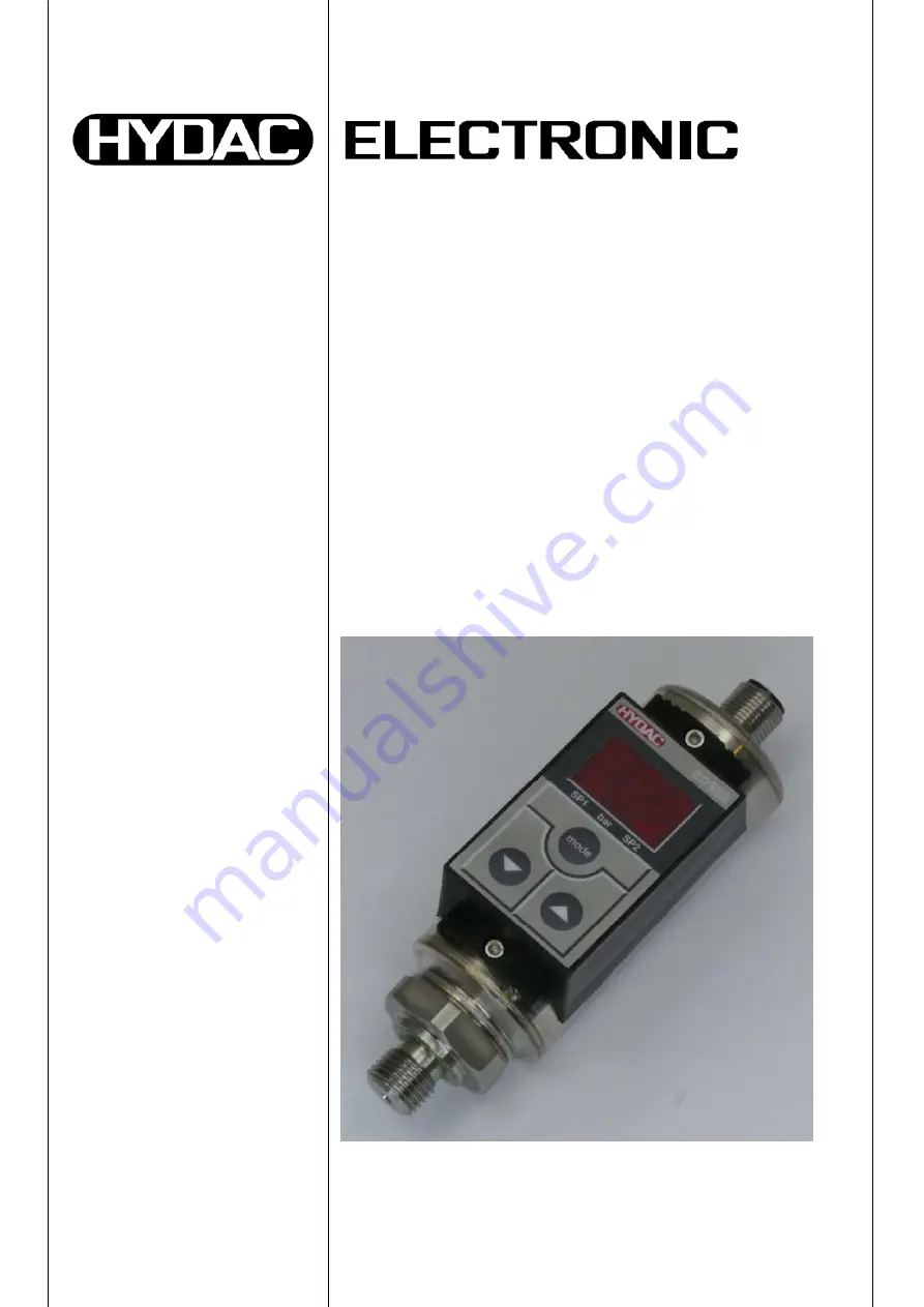
EDS 300 


Summary of Contents for EDS 300

Page 1: ...8 D E F Bedienungsanleitung Originalanleitung User Manual Translation of original instruction Notice d utilisation Traduction de l original Elektronischer Druckschalter Electronic Pressure Switch Manocontacteur électronique EDS 300 ...

Page 2: ...ALOGAUSGANG 9 8 3 EINSTELLEN DER SCHALTPUNKTE UND HYSTERESEN BZW SCHALTWERTE FÜR DIE FENSTERFUNKTION 9 8 4 EINSTELLBEREICHE FÜR DIE SCHALTAUSGÄNGE 10 9 Grundeinstellungen 10 9 1 ÄNDERN DER GRUNDEINSTELLUNGEN 10 9 2 ÜBERSICHT DER GRUNDEINSTELLUNGEN 11 10 Programmierfreigaben 12 10 1 ÄNDERN DER BETRIEBS PROGRAMMIERFREIGABE 12 10 2 ÄNDERN DER HAUPT PROGRAMMIERFREIGABE 12 11 Fehlermeldungen 13 12 Tech...

Page 3: ... sein Bitte beachten Sie dass die in dieser Dokumentation gemachten Angaben der Gerätetechnik zu dem Zeitpunkt der Literaturerstellung entsprechen Abweichungen bei technischen Angaben Abbildungen und Maßen sind deshalb möglich Entdecken Sie beim Lesen dieser Dokumentation Fehler oder haben weitere Anregungen und Hinweise so wenden Sie sich bitte an HYDAC ELECTRONIC GMBH Technische Dokumentation Ha...

Page 4: ...estimmungsgemäßer Verwendung grundsätzlich betriebssicher Um jedoch Gefahren für Benutzer und Sachschäden infolge falscher Handhabung des Gerätes zu vermeiden beachten Sie bitte die folgenden Sicherheitshinweise Der EDS 300 darf nur in einwandfreiem technischem Zustand benutzt werden Die Verwendungshinweise sind einzuhalten Die Angaben auf dem Typenschild sind zu beachten Störungssuche und Reparat...

Page 5: ...g des als Zubehör erhältlichen Anschlussadapters ZBM 14 kann sichergestellt werden dass sich die Anzeige optimal im Sichtbereich des Anwenders befindet In kritischen Anwendungsfällen z B starke Vibrationen oder Schläge ist der Druckanschluss zur mechanischen Entkopplung über Minimessleitung vorzunehmen Die Befestigung erfolgt dann mittels einer als Zubehör erhältlichen Schelle siehe Kapitel 14 2 Z...

Page 6: ...r eines Schaltpunkts Schalten der Schaltausgänge entsprechend dem Druck und den eingestellten Schaltparametern Analogausgang Menü zur Grundeinstellung Anpassen des EDS 300 an die jeweilige Applikation Programmierfreigaben Es stehen 4 verschiedene Ausgangsvarianten zur Verfügung 1 Schaltausgang 2 Schaltausgänge 1 Schaltausgang und 1 Analogausgang 4 20 mA 2 Schaltausgänge und 1 Analogausgang 4 20 mA...

Page 7: ...eten ist Ebenso kann permanent ein Schaltpunkt angezeigt werden oder die Anzeige dunkel geschaltet werden Je nach Einstellung erscheint nach der Einschaltmeldung kurz TOP S P 1 S P 2 oder OFF in der Anzeige Der aktuelle Druck kann kurzzeitig zur Anzeige gebracht werden indem die Taste oder betätigt wird Dabei wird der Maximalwert zurückgesetzt HINWEISE Übersteigt der aktuelle Druck den Nenndruck d...

Page 8: ...ein unterer Schaltwert eingegeben werden die den Bereich bestimmen Der jeweilige Ausgang schaltet wenn der Druck in diesen Bereich eintritt Bei Verlassen des Bereiches d h wenn der Rückschaltwert erreicht ist schaltet der Ausgang zurück Der untere Rückschaltwert liegt knapp unter dem unteren Schaltwert unterer Schaltwert minus 3 fache Schrittweite siehe Kapitel 8 4 Der obere Rückschaltwert liegt k...

Page 9: ...n Eventuell mit der Taste mode weitere Parameter anwählen und mit den Tasten und die Einstellung ändern Nach 3 Sekunden ohne Tastenbetätigung schaltet die Anzeige zurück die Einstellungen werden gespeichert HINWEISE Erscheint beim Einstellversuch LOC in der Anzeige ist die Programmierung gesperrt Abhilfe Programmierfreigabe n auf ON setzen siehe Kapitel 9 Programmierfreigaben Wird beim Ändern die ...

Page 10: ... 0 0 600 10 0 595 0 15 0 600 5 0 Alle in der Tabelle angegebenen Bereiche sind im Raster der Schrittweite einstellbar 9 Grundeinstellungen Zur Anpassung an die jeweilige Applikation kann das Verhalten des EDS 300 über mehrere Grundeinstellungen verändert werden Diese sind zu einem Menü zusammengefasst 9 1 ÄNDERN DER GRUNDEINSTELLUNGEN HINWEISE Bei aktiviertem Menü werden keine Schaltfunktionen aus...

Page 11: ...nzeige Primär Anzeigewert der permanent in der A nzeige stehen soll ACT aktueller Druck Top Druck Spitzenwert S P 1 oder S P 2 Schaltpunkt 1 oder 2 OFF Anzeige dunkel Funktion siehe K apitel 6 Digitalanzeige ACT Top S P 1 S P 1 OFF ACT Kalibrierung Sensornullpunkt Calibrate YES Der momentane Druck wird als neuer Nullpunkt gespeichert Dies ist im Bereich 3 des Gerätenenndruckes möglich In der Anzei...

Page 12: ...DER BETRIEBS PROGRAMMIERFREIGABE mode mode 3 s Druckanzeige 3 s Anzeige Beide Pfeiltasten gleichzeitig betätigen und 3s festhalten Mit oder Einstellung ändern OFF ON Programmierung gesperrt Programmierung frei Pfeiltasten loslassen 10 2 ÄNDERN DER HAUPT PROGRAMMIERFREIGABE Versorgungsspannung abschalten oder Gerät von der Versorgungsspannung trennen mode mode 3 s Druckanzeige 3 s Anzeige Beide Pfe...

Page 13: ...ird angezeigt Abhilfe Korrigieren Sie die Einstellungen E 10 Bei den abgespeicherten Einstellungen wurde ein Datenfehler erkannt Mögliche Ursachen sind starke elektromagnetische Störungen oder ein Bauteildefekt Abhilfe Überprüfen Sie alle Einstellungen Programmierfreigaben Schaltpunkte Rückschaltpunkte und Grundeinstellungen und korrigieren Sie diese gegebenenfalls Sollte der Fehler öfter auftrete...

Page 14: ...FS C max Temperaturkompensation Spanne 0 02 FS C typ 0 03 FS C max Wiederholbarkeit 0 5 FS max Reaktionszeit ca 10 ms Langszeitdrift 0 3 FS typ Jahr Umgebungsbedingungen Kompensierter Temperaturbereich 10 70 C Betriebstemperaturbereich 25 80 C Lagertemperaturbereich 40 80 C Mediumstemperaturbereich 25 80 C Zeichen EN 61000 6 1 2 3 4 Vibrationsbeständigkeit nach DIN EN 60068 2 6 bei 10 500 Hz 10 g ...

Page 15: ...BH Mat Nr 669648 D 13 Anschlussbelegung 13 1 VERSORGUNGSSPANNUNG SCHALTAUSGÄNGE ANALOGAUSGANG Ausführung mit 1 Schaltausgang Stecker EN 175301 803 DIN 43650 3 pol PE Pin 1 UB 2 0 V 3 SP 1 Gehäuse Stecker 4 pol M12x1 Pin 1 UB 2 n c 3 0 V 4 SP 1 1 3 2 ...

Page 16: ...0 Stand 19 09 2018 HYDAC ELECTRONIC GMBH Mat Nr 669648 D Ausführung mit 2 Schaltausgängen Stecker 4 pol Binder Serie 714 M18 Pin 1 UB 2 0 V 3 SP 1 4 SP 2 Stecker 4 pol M12x1 Pin 1 UB 2 SP 2 3 0 V 4 SP 1 2 3 1 4 ...

Page 17: ...g mit 1 Schaltausgang und 1 Analogausgang Stecker 4 pol Binder Serie 714 M18 Pin 1 UB 2 0 V 3 SP 1 4 Analog Stecker 4 pol M12x1 Pin 1 UB 2 Analog 3 0 V 4 SP 1 Ausführung mit 2 Schaltausgängen und 1 Analogausgang Stecker 5 pol M12x1 Pin 1 UB 2 Analog 3 0 V 4 SP 1 5 SP 2 2 3 1 4 ...

Page 18: ...ten 1 2 und 3 ohne Kupplungsdose 8 Gerätestecker M12x1 5 pol nur für Ausgangsvariante 5 ohne Kupplungsdose Ausgang 1 1 Schaltausgang nur in Verbindung mit elektr Anschlussart 5 oder 6 2 2 Schaltausgänge nur in Verbindung mit elektr Anschlussart 4 oder 6 3 1 Schalt und 1 Analogausgang nur in Verbindung mit elektr Anschlussart 4 oder 6 5 2 Schaltausgänge und 1 Analogausgang nur in Verbindung mit ele...

Page 19: ...ZBE 01 Kupplungsdose EN175301 803 DIN 43650 3 pol PE abgewinkelt Kabeldurchmesser 4 5 7 mm Material Nr 905701 ZBE 02 Kupplungsdose Binder Serie 714 M18 4 pol gerade Kabeldurchmesser 6 5 8 mm Material Nr 609479 ZBE 03 Kupplungsdose Binder Serie 714 M18 4 pol abgewinkelt Kabeldurchmesser 6 5 8 mm Material Nr 609480 ...

Page 20: ...upplungsdose M12x1 abgewinkelt mit 5 m Leitung Material Nr 6006789 Farbkennung Pin 1 braun Pin 2 weiß Pin 3 blau Pin 4 schwarz ZBE 06S 03 4 pol Kupplungsdose M12x1 gerade mit 3 m Leitung geschirmt Material Nr 6098243 ZBE 06S 05 4 pol Kupplungsdose M12x1 gerade mit 5 m Leitung geschirmt Material Nr 6143284 ZBE 06S 05 4 pol Kupplungsdose M12x1 abgewinkelt mit 5 m Leitung geschirmt Material Nr 604489...

Page 21: ...x1 abgewinkelt mit 5 m Leitung Material Nr 6006791 Farbkennung Pin 1 braun Pin 2 weiß Pin 3 blau Pin 4 schwarz Pin 5 grau ZBE 08S 02 5 pol Kupplungsdose M12x1 abgewinkelt mit 2 m Leitung geschirmt Material Nr 6019455 ZBE 08S 05 5 pol Kupplungsdose M12x1 abgewinkelt mit 5 m Leitung geschirmt Material Nr 6019456 ZBE 08S 10 5 pol Kupplungsdose M12x1 abgewinkelt mit 10m Leitung geschirmt Material Nr 6...

Page 22: ... Montage Dämpfungsstreifen in die Vertiefung der Bodenplatte einkleben Bodenplatte montieren die Oberseite ist durch Beschriftung OBEN TOP und 2 Pfeile gekennzeichnet EDS 300 einsetzen Schellenspange aufsetzen nur in einer Lage möglich und an den Bügeln festdrücken bis diese einrastet ZBM 310 Schelle zur Wandbefestigung des EDS 300 Werkstoffe Polypropylen Aluminium AlSi12 Stahl Montage Grundplatte...

Page 23: ...EDS 300 23 Stand 19 09 2018 HYDAC ELECTRONIC GMBH Mat Nr 669648 D 16 Geräteabmessungen ...

Page 24: ...EMS SERVICES zur Verfügung HYDAC SYSTEMS SERVICES GMBH Hauptstr 27 D 66128 Saarbrücken Germany Tel 49 0 6897 509 1936 Fax 49 0 6897 509 1933 Anmerkung Die Angaben in dieser Bedienungsanleitung beziehen sich auf die beschriebenen Betriebsbedingungen und Einsatzfälle Bei abweichenden Einsatzfällen und oder Betriebsbedingungen wenden Sie sich bitte an die entsprechende Fachabteilung Bei technischen F...

Page 25: ...Part No 669648 Status 19 09 2018 E User Manual Translation of original instruction Electronic Pressure Switch EDS 300 ...

Page 26: ...8 8 2 ANALOGUE OUTPUT 9 8 3 SETTING THE SWITCHING POINTS HYSTERESES AND OR SWITCHING VALUES FOR THE WINDOW FUNCTION 9 8 4 SETTING RANGES FOR SWITCHING OUTPUTS 10 9 Basic settings 10 9 1 ALTERING THE BASIC SETTINGS 10 9 2 SUMMARY OF THE BASIC SETTINGS 11 10 Programming enables 12 10 1 ALTERING THE OPERATING PROGRAMMING ENABLE 12 10 2 ALTERING THE MAIN PROGRAMMING ENABLE 12 11 Error messages 13 12 T...

Page 27: ...e note the specifications outlined in this documentation for the device technology are correct at the time of publishing Deviations are therefore possible for technical specifications figures and dimensions Should you discover errors when reading this document or if you have any suggestions or remarks please let us know HYDAC ELECTRONIC GMBH Technische Dokumentation Hauptstraße 27 66128 Saarbrücke...

Page 28: ...rder to avoid any risk to the operator or any damage due to incorrect handling of the unit please adhere strictly to the following safety instructions The EDS 300 must not be put into service if any known defects either electrical or mechanical are apparent The instructions for use must be strictly adhered to Read the specifications on the rating plate Troubleshooting and repair work may only be c...

Page 29: ... 2 The connection adaptor ZBM 14 is available as an accessory and is designed to ensure that the display is always visible to the user When used in critical applications e g strong vibrations or knocks the pressure connection must be mechanically decoupled via a Minimess hose Mounting clamps are available as an accessory see point 14 2 Accessories for mechanical connection The electrical connectio...

Page 30: ...g point Switching the switching outputs according to the pressure and the pre set switching parameters Analogue output Menu for basic settings adapting the EDS 300 to the particular application Two different types of programming enable Four different output models are available 1 switching output 2 switching outputs 1 switching output and 1 analogue output 4 20 mA 2 switching outputs and 1 analogu...

Page 31: ...t re set A switching point can likewise be permanently displayed or the display can be switched off Depending on the setting TOP S P 1 S P 2 or OFF appears briefly on the display following the switch on message The actual pressure can be displayed briefly by pressing the or the key This causes the maximum value to be re set NOTE If the actual pressure exceeds the nominal pressure of the unit it ca...

Page 32: ...lue can be input to determine the range The relevant output switches when the pressure enters this range When leaving the range i e when the switch back value has been reached the output switches back The lower switch back value is just below the lower switching value lower switching value minus three times the increment see point 8 4 The upper switch back value is just above the upper switching v...

Page 33: ...ting Use the mode key to call up other parameters if required and alter the setting using the and the keys If no keys are pressed for 3 seconds the display changes back and the settings are saved NOTE If LOC appears in the display when trying to alter the settings programming is disabled locked Action set programming enable to ON see point 9 Programming enable If the or the key is held down during...

Page 34: ... 0 0 400 4 0 398 0 6 0 400 2 0 0 600 10 0 595 0 15 0 600 5 0 All ranges given in the table are adjustable by the increments shown 9 Basic settings In order to adapt the unit to a particular application the function of the EDS 300 can be altered via several basic settings These are combined in one menu 9 1 ALTERING THE BASIC SETTINGS NOTE When the menu is activated no switching operations are carri...

Page 35: ...ary display Primary Display value which should remain permanently displayed ACT actual pressure Top pressure peak value S P 1 or S P 2 switching point 1 or 2 OFF display off for function see point 6 Digital display ACT Top S P 1 S P 1 OFF ACT Calibration of sensor zero point Calibrate YES The base pressure is saved as the new zero point This is possible in the range 3 of the unit s nominal pressur...

Page 36: ...lterations 10 1 ALTERING THE OPERATING PROGRAMMING ENABLE mode mode 3 s pressure 3 s press both arrow keys simultaneously and hold down for 3 s use or to alter setting OFF ON programming disabled programming possible display release arrow keys display 10 2 ALTERING THE MAIN PROGRAMMING ENABLE Switch off supply voltage or disconnect the unit from the supply voltage mode mode 3 s pressure 3 s displa...

Page 37: ...than the switching point the error message is displayed Action Correct the settings E 10 A data error has been detected in the saved settings Possible causes are strong electromagnetic interference or a component fault Action Check all the settings programming enables switching points switch back points and basic settings and correct these if necessary If the errors occur frequently please contact...

Page 38: ...03 FS C max Temperature kompensation range 0 02 FS C typ 0 03 FS C max Repeatability 0 5 FS max Reaction time approx 10 ms Long term drift 0 3 FS typ year Environmental conditions Compensated temperature range 10 70 C Operating temperature range 25 80 C Storage temperature range 40 80 C Fluid temperature range 25 80 C mark EN 61000 6 1 2 3 4 Vibration resistance to DIN EN 60068 2 6 at 10 500 Hz 10...

Page 39: ... GMBH Part No 669648 E 13 Circuit diagram 13 1 SUPPLY VOLTAGE SWITCHING OUTPUTS ANALOGUE OUTPUT Model with 1 switching output Male EN 175301 803 DIN 43650 3 pole PE Pin 1 UB 2 0 V 3 SP 1 Housing Male M12x1 4 pole Pin 1 UB 2 n c 3 0 V 4 SP 1 1 3 2 ...

Page 40: ...300 Status 19 09 2018 HYDAC ELECTRONIC GMBH Part No 669648 E Model with 2 switching outputs Male 4 pole Binder series 714 M18 Pin 1 UB 2 0 V 3 SP 1 4 SP 2 Male M12x1 4 pole Pin 1 UB 2 SP 2 3 0 V 4 SP 1 2 3 1 4 ...

Page 41: ...h 1 switching output and 1 analogue output Male 4 pole Binder series 714 M18 Pin 1 UB 2 0 V 3 SP 1 4 Analogue Male M12x1 4 pole Pin 1 UB 2 Analogue 3 0 V 4 SP 1 Model with 2 switching outputs and 1 analogue output Male M12x1 5 pole Pin 1 UB 2 Analogue 3 0 V 4 SP 1 5 SP 2 2 3 1 4 ...

Page 42: ...possible on output model 5 connector not supplied Output 1 1 switching output only in conjunction with electrical connection type 5 oder 6 2 2 switching outputs only in conjunction with electrical connection type 4 or 6 3 1 switching output and 1 analogue output only in conjunction with electrical connection type 4 or 6 5 2 switching outputs and 1 analogue output only in conjunction with electrica...

Page 43: ...N ZBE 01 Female connector EN175301 803 DIN 43650 3 pole PE right angle Cable diameter 4 5 7 mm Part No 905701 ZBE 02 Female connector Binder Serie 714 M18 4 pole straight Cable diameter 6 5 8 mm Part No 609479 ZBE 03 Female connector Binder Series 714 M18 4 pole right angle Cable diameter 6 5 8 mm Part No 609480 ...

Page 44: ...e Female connector M12x1 right angle with 5 m cable Part No 6006789 Colour code Pin 1 brown Pin 2 white Pin 3 blue Pin 4 black ZBE 06S 03 4 pole Female connector M12x1 straight with 3 m cable shielded Part No 6098243 ZBE 06S 05 4 pole Female connector M12x1 straight with 5 m cable shielded Part No 6143284 ZBE 06S 05 4 pole Female connector M12x1 right angle with 5 m cable shielded Part No 6044891 ...

Page 45: ...ctor M12x1 right angle with 5 m cable Part No 6006791 Colour code Pin 1 brown Pin 2 white Pin 3 blue Pin 4 black Pin 5 grey ZBE 08S 02 5 pole Female connector M12x1 right angle with 2 m cable shielded Part No 6019455 ZBE 08S 05 5 pole Female connector M12x1 right angle with 5 m cable shielded Part No 6019456 ZBE 08S 10 5 pole Female connector M12x1 right angle with 10 m cable shielded Part No 6023...

Page 46: ...lene Mounting Glue damping strips into the recesses of the base plate Mount base plate the top is indicated by OBEN TOP and 2 arrows Insert EDS 300 Fit clip only one possible position and press hard on the cross pieces until they engage ZBM 310 clamp for wall mounting the EDS 300 material polypropylene aluminium AlSi12 steel Mounting Weld on the steel base plate Mount EDS 300 according to the illu...

Page 47: ...EDS 300 23 Status 19 09 2018 HYDAC ELECTRONIC GMBH Part No 669648 E 16 Dimensions seal Male electrical connection Binder series 714 4p elastomer seal ring DIN 3869 Male electrical connection 4p 5p ...

Page 48: ...ease contact HYDAC SYSTEMS SERVICES HYDAC SYSTEMS SERVICES GMBH Hauptstr 27 D 66128 Saarbrücken Germany Tel 49 0 6897 509 1936 Fax 49 0 6897 509 1933 Note The information in this manual relates to the operating conditions and applications described For applications and operating conditions not described please contact the relevant technical department If you have any questions suggestions or encou...

Page 49: ...Code article 669648 Edition 19 09 2018 F Notice d utilisation Traduction de l original Manocontacteur électronique EDS 300 ...

Page 50: ...NTS DE COMMUTATION ET D HYSTÉRÉSIS OU VALEURS LIMITES POUR FONCTION FENETRE 9 8 4 PLAGES DE RÉGLAGE POUR LES SORTIES DE COMMUTATION 10 9 Réglages de base 10 9 1 MODIFICATION DES RÉGLAGES DE BASE 10 9 2 APPERÇU DES RÉGLAGES DE BASE 11 10 Autorisation de programmation 12 10 1 MODIFICATION DE L AUTORISATION DE PROGRAMMATION BASSE 12 10 2 MODIFICATION DE L AUTORISATION DE PROGRAMMATION HAUTE 12 11 Cod...

Page 51: ... lieu d utilisation Veuillez noter que les informations fournies dans cette documentation correspondent à la technique de l appareil au moment de l élaboration de ce document Pour cette raison les différentes données techniques illustrations et mesures sont susceptibles de diverger Si lors de la lecture de cette documentation vous deviez détecter des erreurs ou encore si vous aviez des suggestions...

Page 52: ...umains ou matériels suite à une mauvaise utilisation de l appareil veuillez prendre connaissance des points suivants L EDS 300 ne doit être mis en service que s il est dans un état technique et visuel irréprochable Les instructions de montages suivantes sont à respecter impérativement Respecter les indications de la plaque signalétique La recherche de pannes et les réparations ne peuvent être effe...

Page 53: ...nes radioactifs ou les substances semblables 4 Montage L EDS 300 peut être monté directement sur un bloc hydraulique par l intermédiaire du raccordement process G 1 4A ISO 1179 2 par l utilisation du raccord d adaptation ZBM 14 il est garanti que l indicateur sera lisible par l utilisateur Dans des cas d utilisation critiques par ex vibrations ou chocs importants le raccordement hydraulique doit ê...

Page 54: ...t d enclenchement Commutation des sorties sur seuil correspondant à la pression actuelle et aux paramètres de commutation réglés Sortie analogique Menu pour réglages de base adaptation de l EDS 300 à l application Protection de programmation 4 variantes existent 1 sortie de commutation 2 sorties de commutation 1 sortie de commutation et 1 sortie analogique 4 20 mA 2 sorties de commutation et 1 sor...

Page 55: ...ière réinitialisation De la même manière il peut être affiché en permanence la valeur du seuil d enclenchement ou de laisser l affichage éteint Selon le choix effectué il apparaît à la mise sous tension TOP SP1 SP2 ou OFF La pression actuelle pourra être affichée brièvement en actionnant la touché ou et réinitialisera la fonction valeur maximale REMARQUE Si la valeur actuelle dépasse la pression n...

Page 56: ...trer un minimum et un maximum permettant de delimiter la plage à surveiller La sortie commute quand la pression se situe dans l intervalle donné En sortant de cette plage ce qui signifie que le point de réenclenchement est atteint la sortie rebascule La valeur basse de réenclenchement se trouve légèrement en dessous de la limite basse de la plage surveillée valeur de commutation 3 x le pas de prog...

Page 57: ...ffichées Passer alors au pas de programme suivant avec mode etc Après 3 secondes sans appuyer sur une des touches les valeurs alors affichées sont sauvegardées et l affichage initial est alors redonné mode 2 s 3 s Valeur de Affichage Régler le seuil mode pour augmenter pour diminuer Appuyer sur la touche mode jusqu à obtenir le bon paramètre pression REMARQUE S il apparaît LOC à l affichage lors d...

Page 58: ...ndantes du pas 9 Réglages de base Pour permettre à l ED S 300 d adapter son comportement à tous les cas d application vous pouvez modifier les réglages de base regroupés dans un menu de base 9 1 MODIFICATION DES RÉGLAGES DE BASE REMARQUE En activant ce menu les fonctions de commutations ne sont pas pas actives Couper la tension d alimentation ou veiller à déconnecter l appareil Sortir du menu régl...

Page 59: ...permanente en fonctionnement normal ACT Pression actuelle Top Affichage de la valeur crête S P 1 ou S P 2 Seuil 1 ou 2 OFF Affichage inactive Voir chapitre 6 Affichage digital ACT Top S P 1 S P 1 OFF ACT Calibration du zéro du capteur Calibrate YES La pression actuelle est prise comme zéro Cette calibration est possible dans un domaine de 3 de la pression nominale de l appareil Il apparaît new qua...

Page 60: ...N DE PROGRAMMATION BASSE se fait dans le menu courant mode mode 3 s Valeur de 3 s Affichage Appuyer en simultané Avec ou modifier le réglage OFF ON pas d autorisation programmation programmation autorisée sur ou pendant 3 secondes relâcher les touches pression 10 2 MODIFICATION DE L AUTORISATION DE PROGRAMMATION HAUTE se fait dans le menu de base Couper la tension d alimentation ou veiller à décon...

Page 61: ...t de la plage de fonctionnement Remède Corriger les réglages E 10 Lors de la sauvegarde des réglages une erreur a été détectée La cause provient sûrement de perturbations électromagnétiques ou d un défaut matériel Remède Vérifier tous les réglages autorisation de programmation seuils déclenchement et réglages de base et corriger en le cas d erreur Si cette erreur devait revenir souvent veuillez vo...

Page 62: ...ue 0 02 PE C typ 0 03 FS C max Répétabilité 0 5 PE max Temps de réaction env 10 ms Dérive dans le temps 0 3 FS typ année Conditions environnementales Plage de température compensée 10 70 C Plage de température de service 25 80 C Plage de température de stockage 40 80 C Plage de température du fluide 25 80 C Sigle EN 61000 6 1 2 3 4 Resistance aux vibrations selon DIN EN 60068 2 6 à 10 500 Hz 10 g ...

Page 63: ...9648 F 13 Configuration des sorties 13 1 TENSION D ALIMENTATION SORTIES DE COMMUTATION SORTIE ANALOGIQUE Exécution avec 1 sortie de commutation Embase EN 175301 803 DIN 43650 3 pôles PE Pin 1 UB 2 0 V 3 SP 1 Boîte Embase 4 pôles M12x1 Pin 1 UB 2 n c 3 0 V 4 SP 1 1 3 2 ...

Page 64: ...n 19 09 2018 HYDAC ELECTRONIC GMBH Code article 669648 F Exécution avec 2 sorties de commutation Embase 4 pôles série Binder 714 M18 Pin 1 UB 2 0 V 3 SP 1 4 SP 2 Embase 4 pôles M12x1 Pin 1 UB 2 SP 2 3 0 V 4 SP 1 2 3 1 4 ...

Page 65: ... de commutation et 1 sortie analogique Embase 4 pôles série Binder 714 M18 Pin 1 UB 2 0 V 3 SP 1 4 Analogique Embase 4 pôles M12x1 Pin 1 UB 2 Analogique 3 0 V 4 SP 1 Exécution avec 2 sorties de commutation et 1 sortie analogique Embase 5 pôles M12x1 Pin 1 UB 2 Analogique 3 0 V 4 SP 1 5 SP 2 2 3 1 4 ...

Page 66: ...mbase M12x1 5 pôles pour variante de sortie 5 sans connecteur Sortie 1 1 sortie de commutation avec raccordement électrique 5 ou 6 2 2 sorties de commutation avec raccordement électrique 4 ou 6 3 1 sortie de commutation et 1 sortie analogique avec raccordement électrique 4 ou 6 5 2 sorties de commutation und 1 sortie analogique avec raccordement électrique 8 Plage de pression en bar 016 040 100 25...

Page 67: ... ÉLECTRIQUE ZBE 01 Connecteur EN175301 803 DIN 43650 3 pôles PE coudé Diamètre de câble 4 5 7 mm Code article 905701 ZBE 02 Connecteur Binder série 714 M18 4 pôles droit Diamètre de câble 6 5 8 mm Code article 609479 ZBE 03 Connecteur Binder série 714 M18 4 pôles coudé Diamètre de câble 6 5 8 mm Code article 609480 ...

Page 68: ... pôles Connecteur M12x1 coudé avec 5 m de câble Code article 6006789 Code de couleur Pin 1 brun Pin 2 blanc Pin 3 bleu Pin 4 noir ZBE 06S 03 4 pôles Connecteur M12x1 droit avec 3 m de câble blindé Code article 6098243 ZBE 06S 05 4 pôles Connecteur M12x1 droit avec 5 m de câble blindé Code article 6143284 ZBE 06S 05 4 pôles Connecteur M12x1 coudé avec 5 m de câble blindé Code article 6044891 Code d...

Page 69: ...ecteur M12x1 coudé avec 5 m de câble Code article 6006791 Code de couleur Pin 1 brun Pin 2 blanc Pin 3 bleu Pin 4 noir Pin 5 gris ZBE 08S 02 5 pôles Connecteur M12x1 coudé avec 2 m de câble blindé Code article 6019455 ZBE 08S 05 5 pôles Connecteur M12x1 coudé avec 5 m de câble blindé Code article 6019456 ZBE 08S 10 5 pôles Connecteur M12x1 coudé avec 10 m de câble blindé Code article 6023102 Code ...

Page 70: ... EDS 300 matière polypropylène Montage Coller la partie élastomère sur l embase Monter l embase en veillant à respecter les flèches et inscriptions OBEN TOP Monter l EDS 300 Monter le collier une seule possibilité de montage en l encliquetant sur l embase ZBM 310 Collier pour montage mural de l EDS 300 matière polypropylène aluminium AlSi12 acier Montage Souder le socle acier Monter l EDS 300 conf...

Page 71: ...EDS 300 23 Edition 19 09 2018 HYDAC ELECTRONIC GMBH Code article 669648 F 16 Dimensions Joint Joint profilé élastomère DIN 3869 Embase série Binder 714 4p Embase série 4p 5p ...

Page 72: ...toute question concernant les réparations HYDAC SYSTEMS SERVICES GMBH Hauptstr 27 D 66128 Saarbrücken Allemagne Tél 49 0 6897 509 1936 Fax 49 0 6897 509 1933 Remarque Les indications de cette notice se réfèrent aux conditions de fonctionnement et cas d utilisation décrits En cas d applications et ou de conditions de service différentes veuillez contacter le service spécialisé correspondant En cas ...

Reviews: