EN 7.1
13.E2/10.17
Spare Parts List
Filter NFD
Change-Over Version
up to 1600 l/min, up to 25 bar
1. MAINTENANCE
1.1 GENERAL
Please follow the maintenance
instructions!
1.2 INSTALLATION
Before fitting the filter into the system,
check that the operating pressure of the
system does not exceed the permitted
operating pressure of the filter.
Refer to the name plate on the filter!
Filters must be flexibly mounted and not
fixed rigidly to the floor or used as a pipe
support.
When installing, ensure that system
forces cannot be transferred to the filter.
A filter with a stand may only be fixed to
the ground if a compensator, expansion
loop or similar device is fitted in the line.
1.3 COMMISSIONING
Check that the correct filter element is
fitted. Screw in cover again by hand
fully and then unscrew by 1/4 turn (the
sealing effect will not be improved by
overtightening). Move the lever to the
centre position and fill filter via the
system.
Spindle setting
Left
Right
Filter in operation
Undo the air bleed screws on the
covers by a maximum of 1 rotation
and vent the filter. Close these again
as soon as oil begins exiting at the air
bleed screws. After that, change over
the lever to a filter side and check filter
for leakage.
1.4 TOOLS REQUIRED FOR
MAINTENANCE
Type Key for clogging indicator or screw
plug
VD 0 A.1
VR 0 A.0
NFD
AF width 27
AF width 19
1.5 TORQUE VALUE FOR CLOGGING
INDICATORS
Type Max. torque
VM
33 Nm
VR
33 Nm
15 Nm ( for B, BM F, LE and LZ
indicators)
2. CHANGING THE ELEMENT
2.1 REMOVING THE ELEMENT
1. Turn lever through 90° – filtration is
switched over to the other side.
2. Loosen air bleed screw(s) (if present);
remove oil drain plug(s);
Drain oil into a container (the oil must
no longer be fed to the system in an
uncleaned state!).
3. Unscrew cover.
4. Remove filter element(s) with dirt
retainer (if present) from the element
spigot. Examine element surface for
dirt residues and larger particles since
these can be an indication of damage
to components.
5. Remove dirt retainer (if present) by
turning anti-clockwise – bayonet fitting
(only on Version 1.x)
6. Replace or clean filter element(s)
(only W/HC and V elements can be
cleaned).
7. Clean housing, cover and dirt retainer
(if present).
8. Examine filter, especially sealing
surfaces, for mechanical damage.
9. Check O-rings – and replace if
necessary
2.2 FITTING THE ELEMENT
1. Lubricate the O-ring with clean
operating fluid. Apply aluminium paste
or another suitable lubricant to threads
on filter head and bowl.
2. When fitting a new filter element,
check that the designation
corresponds to that of the old element.
3. If present, fit the dirt retainer onto
the new or cleaned filter element by
turning clockwise (only for Version
1.x).
4. Place filter element(s) carefully onto
the element spigot in the housing (if
applicable, observe clip position on the
element, change over as necessary!).
5. Screw the cover on by hand fully and
then a quarter-turn back again.
6. Screw in oil drain plug(s).
7. Move the lever into centre position and
fill the filter side until oil exits from the
air bleed screw.
8. Close the air bleed screw again and
unscrew cover by one quarter-turn.
9. Change lever back to the non-changed
filter side.
10. Check the filter for leakage.
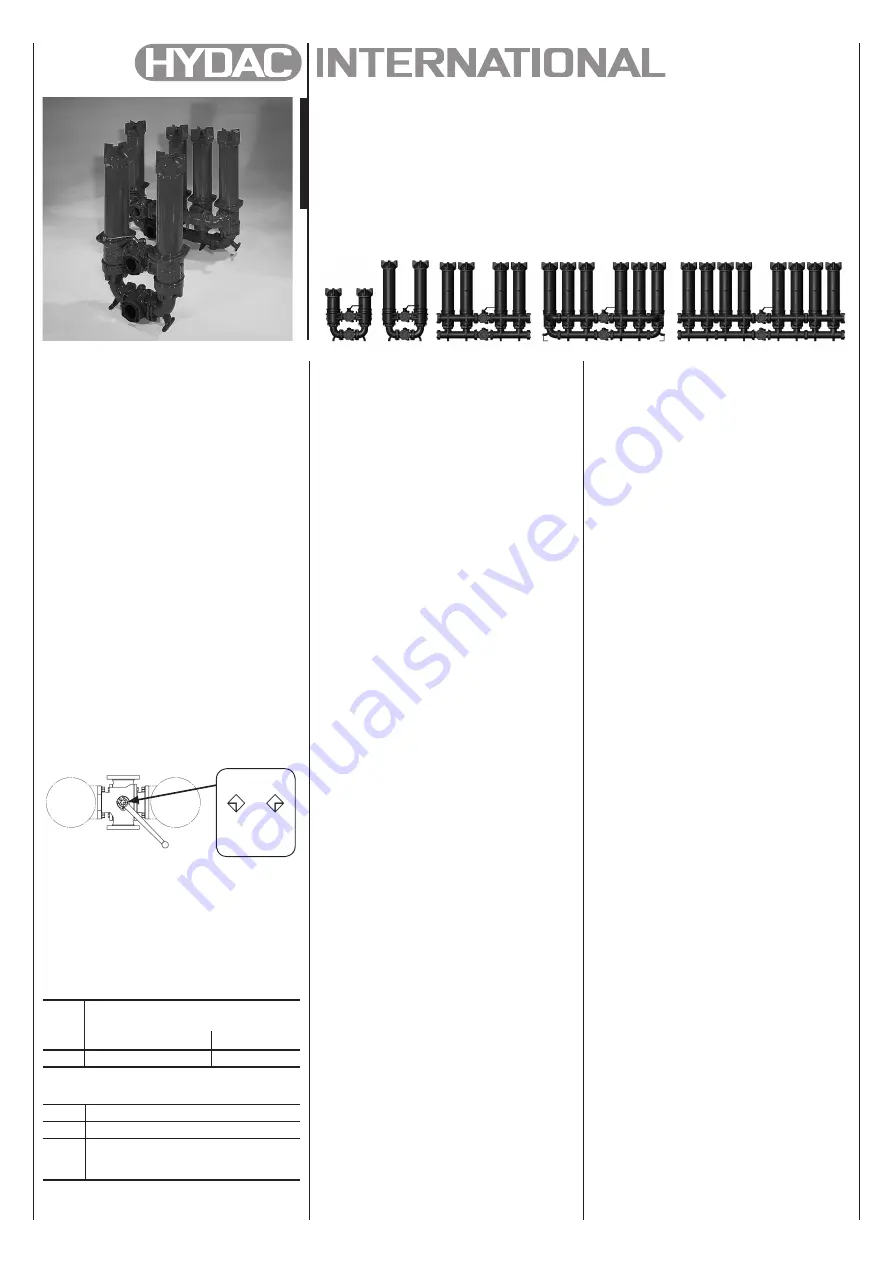
NFD
1340
NFD
2640
NFD
5240
NFD
7840
NFD
10440
NOTICE:
When replacing the pipe elbows and
connection parts, you must ensure
that the parts are assembled without
being placed under strain. If this is not
observed, the aluminium parts may be
damaged.
Filter elements which cannot be cleaned
must be disposed of in accordance with
environmental protection regulations.


