background image

HYDAC FILTER SYSTEMS GMBH

Rectifying malfunctions | 6

MoWa CMP43x0-5 4191543c en-us print

41 / 60

6 Rectifying malfunctions

The following errors could occur when handling or operating
the ConditionMonitoring Package CMP:

Error

Cause(s)

Rectification

No function.

The motor pump
group does not
turn.

No electric
tension.

Check the feed
line, fuse and
the switch.

The pump is
blocked.

Contact HYDAC
Service.

No oil flow.

The motor pump
group is
switched off.

Switch the motor
pump group on.

The electric
motor turns. The
pump does not
convey any fluid.

The magnetic
coupling
between the
electric motor
and pump
makes noises
and becomes
hot.

Switch off the
CMP.

Check the
temperature of
the pump with a
thermometer.
Switch on the
CMP again only
above ≤ 50 °C.

Check whether
the return line is
open.

Check the
pressure setting
of the load
holding valve. If
required, correct
it.

The strainer is
choked.

Change the
strainer.

The viscosity of
the fluid is too
high.

Check the
viscosity of the
fluid.

1

2

3

4

5

6

7

8

A

Summary of Contents for CMP 43x0-5 Series

Page 1: ... ConditionMonitoring Package Installation and Maintenance Instructions English translation of original instructions Document No 4191543c Follow these instructions for proper and safe use Keep for future reference ...

Page 2: ...om Court of Registration Saarbrücken HRB 17216 Executive directors Mathias Dieter Dipl Kfm Wolfgang Haering CE Documentation Representative Günter Harge c o HYDAC International GmbH Industriegebiet 66280 Sulzbach Saar Germany Telephone 49 6897 509 1511 Fax 49 6897 509 1394 E mail guenter harge hydac com UKCA Authorized representative of the manufacturer HYDAC Technology Limited De Havilland Way Wi...

Page 3: ...rmation 10 1 3 Exclusion of liability warranty 11 1 4 Notes on copyright 11 2 Safety 12 2 1 Target group Required personnel qualification 12 2 2 Hazard symbols pictograms 15 2 3 Danger notifications 17 2 4 Observing regulatory information 20 2 5 Observing environmental precautions 20 3 Product and technical specifications 21 3 1 Technical data 22 3 2 Checking the scope of delivery 24 3 3 Intended ...

Page 4: ...ng reading measurement reports values with FluMoS 40 6 Rectifying malfunctions 41 7 Performing Maintenance 43 7 1 Maintenance table 44 7 2 Visual check for leaks 44 7 3 Visual check of electric equipment 44 7 4 Cleaning Changing the protective screen 44 8 Decommissioning Disposal 47 8 1 Temporary shutdown 47 8 2 Permanent shutdown 47 8 3 Disposal Recycling 47 A Appendix 48 A 1 Contacting Customer ...

Page 5: ...in this manual are meant for general illustration purposes Therefore representations and functional options can deviate from the delivered product We reserve the right to make changes to the contents of this manual without prior notice 1 1 Target group of the manual This manual was created for the following target group Target group Tasks Owner Keep this manual and the applicable documents at the ...

Page 6: ...Product name Operating and Maintenance Instructions Document no 12345678 English translation of original instructions Valid from from s no 1 5 2 4 3 Fig 1 Overview labeling of the title page 1 Short name of the product product name 2 Type of document 3 Language 4 Document no Index 5 Supplementary instructions regarding the validity of the manual optional Please note that you can directly access in...

Page 7: ...product is assembled and connected ü The product is switched off 1 Switch the product on 1 2 3 Representation of procedural instructions In the case of procedural instructions there are the two following representations Procedural instructions with a fixed sequence Procedural instructions the order of which must be strictly adhered to are listed with sequential numbering 1 2 3 etc An example for p...

Page 8: ...ps with intermediate results and end results Intermediate results are the consequence of activities they are marked with an indented arrow End results represent the end of an activity and are repre sented with a flag An example for a procedural instruction with intermediate result and final result 1 Switch the product on ð The display lights up 2 Press the button O The product is now ready for use...

Page 9: ...d of the manual Tip for handling the product Required tool 1 2 6 Representation of warning general safety information All the warning general safety information in this manual are highlighted with pictograms and signal words The pictogram and the signal word give you information of the risk level of the danger Warning General Safety Information which is placed ahead of each activity are represente...

Page 10: ...s a hazardous situation with a medium level of risk which if not avoided can result lethal or serious injury CAUTION CAUTION The signal word indicates a hazardous situation with a low level of risk which if not avoided can result in minor or moderate injury NOTICE NOTICE The signal word indicates a hazardous situation with a high level of risk which if not avoided will result in damage to property...

Page 11: ...mation in these instructions In particular we shall not be liable for lost profit or other financial loss This exclusion of liability does not apply in cases of intent and gross negligence Moreover it does not apply to defects which have been deceitfully concealed or whose absence has been guaranteed nor in cases of culpable harm to life physical injury and damage to health If we negligently breac...

Page 12: ... maintenance work and also troubleshooting on the product An owner is the person who operates the product himself herself for commercial or economic purposes or provides it to a third party for use application and bears the legal product responsibility to protect the user the personnel or the third party The obligations of the owner are To know and apply the applicable health and safety regu latio...

Page 13: ... is required Installation Specialist personnel Mechanical Specialist personnel Electrical Safe handling use of tools Product specific knowledge is required Commissioning Specialist personnel Mechanical Specialist personnel Electrical Safe handling use of tools Product specific knowledge is required Handling operation operation moni toring Operating personnel General Product specific knowledge is r...

Page 14: ...sport Installation Commissioning Operation Troubleshooting Maintenance Disposal Specialist personnel Administrator Trained and appointed by the owner Maintenance and repair personnel Service personnel Administrator Extensive experience of the product transport Commis sioning Operation Troubleshooting Maintenance Disposal Specialist personnel Service Admin istrator Service personnel Administrator H...

Page 15: ...lete and legible Warning signs used These marks can be found for all safety and warning instruc tions in this manual which indicate particular dangers to persons property or the environment Danger point warning Dangerous electrical voltage warning Signs used for giving orders These symbols can be found for all safety and warning instruc tions in this manual which indicate particular dangers to per...

Page 16: ... due to operating pressure Signs used for the required specialist personnel These symbols show the required training knowledge for installation work and or maintenance work Specialist personnel General Operating personnel These persons have a specialist training and several years of work experience They are able to assess and perform the work assigned to them and they are also able to detect poten...

Page 17: ...ons The following residual risks can occur in the various life phases of the product Life phase Installation Assembly The following risks could arise during the installation assembly life phase DANGER Electric voltage warning Danger of fatal injury u In case of any damage to the insulation switch off the supply voltage immediately and arrange for repairs to be carried out u Before carrying out any...

Page 18: ...ife phase Environmentally tip Open ports Oil leaking out from open ports u Soak up the leaking oil with an absorbent cloth and dispose of it in an environmentally friendly way Life phase Commissioning Operation The following risks could arise during the commissioning operation life phase CAUTION Hot surfaces between electric motor and pump Risk of burns u Allow the magnetic coupling to cool down L...

Page 19: ...irs to be carried out u Before carrying out any work on the electrical system and before any maintenance cleaning or repair work disconnect the supply line or pull out the power plug u Never bypass the fuses or disable them u Keep moisture away from live parts WARNING The hydraulic system is under operating pressure Danger of bodily injury u The hydraulic system must be depressurized before perfor...

Page 20: ...rements Country specific regulations organization specific regula tions Occupational safety rules 2 5 Observing environmental precautions Take all measures to protect the environment Ensure that no operating medium is released into the environment soil or water Environmentally tip Operating fluid operating medium is released into the soil or water Environmental hazard u Remove any escaped operatin...

Page 21: ...n terms of size and material properties ferromagnetic non ferromagnetic and also counted Furthermore the CMP Oil Condition Sensor HydacLab or AquaSensor AS is available as an option The two sensors make it possible to determine the relative water content in the oil specified in percentage saturation where the HydacLab detects liquid contaminants with external fluids mixtures using additional measu...

Page 22: ...missible operating fluid Mineral oils and mineral oil based raffi nates Sealing material FKM Permissible operating pressure PIN 0 4 3 bar POUT 0 5 bar Permissible Viscosity Range in operation 12 20000 mm s Permissible Viscosity Range for measurement 12 20000 mm s Flow 6 ml min 50 Hz 7 ml min 60 Hz Permitted fluid temperature range 0 60 C 32 140 F Tab 3 Technical data Hydraulic data Electrical data...

Page 23: ...r conditions Clean salt free air not near oxidizing substances rust film Storage duration Replace all seals before a commis sioning after a storage time of 2 years Tab 5 Technical data Ambient and storage conditions General data Emission sound pressure level LPA 70 db A Design service life The design service life of the product is not limited if the service and mainte nance intervals are complied ...

Page 24: ...the scope of delivery for completeness The following items are included in the scope of delivery Qty Description 1 CMP model according to the order 1 Technical documentation consisting of Installation and Maintenance Instructions for the CMP43x0 5 this document Operation and maintenance Instructions MCS Certificate of calibration for MetallicContamination Sensor Operating instructions HYDACLab HLB...

Page 25: ... the following Observing all instructions in the instruction manual performing inspection and maintenance work Claims for defects or liability regardless of the legal foun dation do not apply with incorrect or improper installation commissioning usage handling storage maintenance repair use of unsuitable components or other circumstances for which the manufacturer is not responsible The manufactur...

Page 26: ...ny damage resulting from such use This risk is borne solely by the owner Improper use may result in hazards and or will damage the product Examples of improper use include Operation in potentially explosive atmospheres Operation under non approved operational conditions Modifications to the product made by the user or purchaser Inadequate monitoring of parts that are subject to wear and tear Impro...

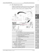
Page 27: ...Always mention the part no and the serial no when contacting HYDAC Fig 2 Decoding the name plate Item Description 1 Type label for ConditionMonitoring Package 2 Name plate of the electric motor 3 Mode code for the ConditionMonitoring Package P N Part no S N Serial number Date Year week of production Motor voltage Voltage Motor grid Number of phases Frequency Frequency Power Power consumption Max F...

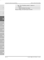
Page 28: ...hnical specifications HYDAC FILTER SYSTEMS GMBH 28 60 MoWa CMP43x0 5 4191543c en us print Max Inlet pressure Operating pressure maximum Weight Weight when empty Sensor voltage Connected load of sensor 1 2 3 4 5 6 7 8 A ...

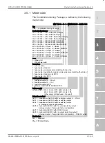
Page 29: ...ithout display 122 CS1000 ISO SAE with display 131 CS1000 ISO SAE NAS without display 132 CS1000 ISO SAE NAS with display 203 CS2000 ISO 4406 1987 NAS 1638 213 CS2000 ISO 4406 1991 NAS 1638 223 CS2000 ISO 4406 1999 SAE AS 4059 431 MCS1000 70µm RS485 437 MCS1000 70µm RS485 Ethernet 441 MCS1000 100µm RS485 447 MCS1000 100µm RS485 Ethernet 451 MCS1000 200µm 1 RS485 457 MCS1000 200µm 1 RS485 Ethernet ...

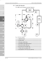
Page 30: ... 3 6 Hydraulic diagram The CMP has the following hydraulic diagram Fig 4 Hydraulic diagram 1 Electric motor 2 Gear pump 3 Pressure relief valve 4 MetallicContamination Sensor 5 Suction strainer 600 µm 6 Suction port connection IN 7 Return port connection OUT 8 AquaSensor HYDACLab optional 1 2 3 4 5 6 7 8 A ...

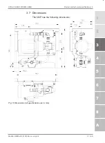
Page 31: ...ER SYSTEMS GMBH Product and technical specifications 3 MoWa CMP43x0 5 4191543c en us print 31 60 3 7 Dimensions The CMP has the following dimensions Fig 5 Dimensions all specifications are in mm 1 2 3 4 5 6 7 8 A ...

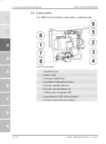
Page 32: ...nts The CMP has the following components operating parts Fig 6 Components 1 Electric motor 2 Gear pump 3 Pressure relief valve 4 MetallicContamination Sensor 5 Suction strainer 600 µm 6 Suction port connection IN 7 Return port connection OUT 8 AquaSensor HYDACLab option 9 Sensor connection box option 1 2 3 4 5 6 7 8 A ...

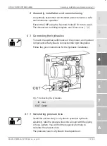
Page 33: ...necting the hydraulics To reach the optimal performance of the product an important component is the hydraulic connection the right integration Follow the given instructions for the hydraulic installation Fig 7 Connecting the hydraulics IN Inlet OUT Outlet 4 1 1 Calculating pressure loss Install the unit securely in a hydraulic system a hydraulic assembly take the pressure loss into account with t...

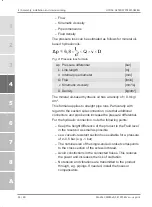
Page 34: ...articularly with regard to the suction side connection note that additional connectors and pipe bends increase the pressure differential For the hydraulic connection note the following points Keep the height difference of the product to the Fluid level in the reservoir as small as possible se a vacuum resistant suction hose suitable for a pressure of 0 5 bar e g 1 bar The nominal size of the singl...

Page 35: ...vel of contamination is found at the bottom of the tank All impurities and other particles are deposited on the bottom of the tank NOTICE Overpressure at the suction port connection The pump will be damaged destroyed u Observe the permissible pressure at the suction port IN 4 1 3 Connecting outlet OUT Use a hose or pipeline for the connection OUT The nominal size of the hose or pipeline should cor...

Page 36: ... insulation switch off the supply voltage immediately and arrange for repairs to be carried out u Before carrying out any work on the electrical system and before any maintenance cleaning or repair work disconnect the supply line or pull out the power plug u Never bypass the fuses or disable them u Keep moisture away from live parts MetallicContamination Sensor MCS1000 to be electrically connected...

Page 37: ...combined and connected to terminals or plugs For the assignment of the interfaces and descriptions refer to the technical documentation contained in the scope of delivery for example installation drawing Modbus TCP protocol description 4 2 1 Connecting the electric motor 1 phase Connect the supply voltage in the terminal box of the electric motor Connecting terminals L N PE 4 2 2 Connecting the el...

Page 38: ...ta connection Checking the direction of rotation Check the direction of rotation on the electric motor by switching it on briefly manual operation An arrow on the fan shroud pump shows the correct direction of rotation If it is necessary to modify the direction of rotation then switch the two phases in the terminal box of the electric motor 1 2 3 4 5 6 7 8 A ...

Page 39: ...c en us print 39 60 4 3 Commissioning ü The CMP is connected hydraulically and electrically 1 Switch on the hydraulic system 2 Open the existing shut off devices upstream or down stream the CMP 3 Check for leaks Eliminate leakages immediately O The commissioning is complete 1 2 3 4 5 6 7 8 A ...

Page 40: ...ent reports values with FluMoS The FluidMonitoring Software FluMoS is used to read and analyze measurement reports measured values from the HYDAC sensors interfaces or devices FluMoS light is available for download on the homepage www hydac com Free download 3 sensors can be read evaluated FluMoS professional can be purchased as an accessory With costs 2 sensors which can be read evaluated paramet...

Page 41: ...vice No oil flow The motor pump group is switched off Switch the motor pump group on The electric motor turns The pump does not convey any fluid The magnetic coupling between the electric motor and pump makes noises and becomes hot Switch off the CMP Check the temperature of the pump with a thermometer Switch on the CMP again only above 50 C Check whether the return line is open Check the pressure...

Page 42: ... 5 4191543c en us print Error Cause s Rectification Heat the fluid to achieve the permissible viscosity The transport seals have not been removed Remove the transport seals The transport seals are the yellow plastic parts Tab 8 Error cause rectification 1 2 3 4 5 6 7 8 A ...

Page 43: ...of any damage to the insulation switch off the supply voltage immediately and arrange for repairs to be carried out u Before carrying out any work on the electrical system and before any maintenance cleaning or repair work disconnect the supply line or pull out the power plug u Never bypass the fuses or disable them u Keep moisture away from live parts WARNING The hydraulic system is under operati...

Page 44: ...el Mechanical 7 2 Visual check for leaks With a visual check check the hydraulic connections and components for leaks If there are leaks switch off the unit system immediately and eliminate the leaks immediately 7 3 Visual check of electric equipment Check the electrical components cables cable glands switches sensors etc visually for damage Allow the damaged parts to be replaced immediately 7 4 C...

Page 45: ...aning the protective screen To clean change the protective screen proceed as follows ü The motor pump group is switched off ü The hydraulic system is depressurized 1 Unscrew the screw plug 1 with a wrench 22 mm in a counterclockwise direction ð Operating fluids can escape depending on the mounting position 2 Remove the strainer insert 3 and clean it 3 Check strainer insert 3 and the seal ring 2 on...

Page 46: ...7 Performing Maintenance HYDAC FILTER SYSTEMS GMBH 46 60 MoWa CMP43x0 5 4191543c en us print O The cleaning changing of the suction strainer is complete 1 2 3 4 5 6 7 8 A ...

Page 47: ...manently proceed as follows Empty the product fully including all the components before the shutdown Fully disconnect the product from the surrounding units Slacken or remove the electric pneumatic or hydraulic connections insofar as they are present 8 3 Disposal Recycling Dismount and recycle the product that cannot be used any more not as a whole unit but in individual parts and according to the...

Page 48: ... e mail and mailing addresses for the Hotline product support Customer Service Branches service partners for maintenance repair and spare parts can be found always updated on our homepage www hydac com HYDAC SYSTEMS SERVICES GMBH Friedrichsthaler Str 15 Werk 13 66450 Neunkirchen Heinitz Germany Telephone 49 6897 509 01 Fax 49 6897 509 324 E mail service hydac com Homepage www hydac com Tab 9 HYDAC...

Page 49: ...cces sories make sure to always indicate the exact model code and the serial number Ite m Description Qty Part no Suction strainer fitting with suction strainer 600 µm complete 1 6198570 Suction strainer 600 µm 1 6204717 Seal ring for the suction strainer 1 6033968 MetallicContamination Sens or MCS1000 1 Motor pump group FKM 1 HYDACLab HLB1400 1 AquaSensor AS1000 1 Tab 10 Spare parts list availabl...

Page 50: ...e Description Part no Single ended cordset L 0 5 m ZBE08 005 Line sheath color black 6242152 Single ended cordset L 2 m ZBE08 02 Line sheath color black 6006792 Single ended cordset L 3 m ZBE08 03 Line sheath color black 3847617 Single ended cordset L 5 m ZBE08 05 Line sheath color black 6006791 ZBE30 Connecting line unshielded black Socket M12x1 5 pole A coded Plug M12x1 5 pole A coded Descriptio...

Page 51: ...ting line L 30 m ZBE30 30 Line sheath color black 3656854 ZBE30S Connecting line shielded black Socket M12x1 5 pole A coded Plug M12x1 5 pole A coded Description Part no Connecting line L 10 m ZBE30S 10 Line sheath color black 3729098 ZBE47 Single ended cordset unshielded black Socket M12x1 5 pole A Open cable end 5 pole Description Part no Single ended cordset L 5 m ZBE47 05 Line sheath color bla...

Page 52: ...7S 10 3527627 Single ended cordset L 15 m Line sheath Color black ZBE47S 15 4033085 Connection cable 8 pin ZBE44 Screwed connection bushing shielded Socket M12x1 8 pole A coded Description Part no Screwed connection bushing ZBE44 Color 3281243 ZBE0P Single ended cordset unshielded black Socket M12x1 8 pin angled A coded Open cable end Description Part no Single ended cordset L 2 m ZBE0P 02 Line sh...

Page 53: ...ordset L 2 m ZBE42S 02 black 3281220 Single ended cordset L 5 m ZBE42S 05 black 3281239 Single ended cordset L 10 m ZBE42S 10 black 3449681 Single ended cordset L 20 m ZBE42S 20 black 3654932 ZBE43 Double ended cordset unshielded black Socket M12x1 8 pole A coded Plug M12x1 8 pole A coded Description Part no Double ended cordset L 0 5 m ZBE43 005 Line sheath color black 4193544 1 2 3 4 5 6 7 8 A ...

Page 54: ...verview labeling of the title page 6 Fig 2 Decoding the name plate 27 Fig 3 Model Code 29 Fig 4 Hydraulic diagram 30 Fig 5 Dimensions all specifications are in mm 31 Fig 6 Components 32 Fig 7 Connecting the hydraulics 33 Fig 8 Pressure loss formula 34 Fig 9 Star delta connection 38 Fig 10 Cleaning the protective screen 45 ...

Page 55: ... Required personnel qualification 13 Tab 3 Technical data Hydraulic data 22 Tab 4 Technical data Electrical data 22 Tab 5 Technical data Ambient and storage conditions 23 Tab 6 Technical data General data 23 Tab 7 Checking the scope of delivery 24 Tab 8 Error cause rectification 41 Tab 9 HYDAC Service Germany 48 Tab 10 Spare parts list 49 ...

Page 56: ...able switching outputs In the default settings they are switched in case of a saturation level of 60 SP2 warning and 80 SP1 alarm In addition AS 1000 measures the fluid temperature and also gives this as 4 20 mA Signal off AS 1000 enables a continuous monitoring of hydraulics and lubri cating oils precise permanent and online FluMoS light FluMoS light is available as a download from the homepage a...

Page 57: ...ertions can be made about the condition of an oil e g time deterioration or mixing with other fluids on the basis of the measured values for the relative change in dielectric constant value the electric conduc tivity the saturation level and the temperature These measured values are available as sequential analogue signals and or switching signals at the electrical outlet of the HYDACLAB for examp...

Page 58: ...ce 48 D Disposal Disposal 47 Recycling 47 Documentation Representative 2 E Electric motor Check direction of rotation 38 Connecting 1ph 37 Connecting 3ph 37 Delta connection 38 Star Y connection 38 Star delta connection 38 Emission sound pressure level 23 Exclusion of Liability 11 F Flow 22 FluMoS Download 40 light 40 professional 40 H HLB Connecting 36 Hotline 48 HYDAC Branch offices 48 General T...

Page 59: ...on electrical 22 Pressure loss Calculate hydraulic line 33 Formula for 34 Pressure differential 34 Protection class 22 Publisher 2 Pump type 22 S Sealing material 22 service life design 23 shutdown Permanent 47 Temporary 47 Spare parts Finding 49 Storage duration 23 Storage temperature range 23 Supply voltage 22 T Technical data 22 Ambient conditions 23 Electrical data 22 General data 23 Hydraulic...

Page 60: ...www hydac com ...

Reviews: