5
−
4
37
Use and maintenance manual DM-1215
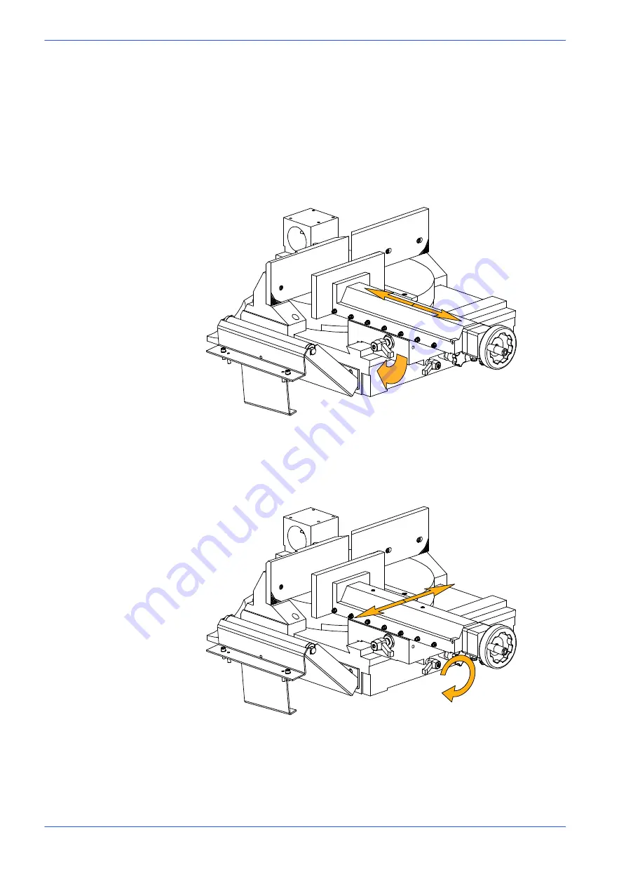
Rapid vice positioning
By means of a simple device the vice can be slid back and forth to accelerate vice
opening and closing operations.
Grip the lever illustrated in the figure below and rotate in a clockwise direc
tion: the vice is now free to slide back and forth to the required position.
Once positioned, release the lever to lock the vice in place.
Finally, position the vice to within 2
−
3 mm of the workpiece using the hand
wheel.
Rapid vice translation
For angled cuts, the vice may be slid to the left or right along the prismatic guide.
Release the locking lever illustrated in the figure below.
Position the vice to the right or left and lock the lever.
Width of cut
The machine is fitted with protections which protect the entire blade stroke,
leaving exposed only the part of the blade required to make the cut itself as
specified by current standards. The width of the cut is determined by the
longitudinal section of the workpiece, so that only the part of the blade required
to make the cut is actually exposed.
Summary of Contents for DM-1215
Page 1: ...USE AND MAINTENANCE MANUAL YEAR OF MANUFACTURE ______________ DM 1215 EN ...
Page 2: ......
Page 4: ......
Page 34: ......
Page 53: ...6 7 52 Diagrams exploded views and replace Standardised Wiring Diagrams ...
Page 54: ...6 8 53 Use and maintenance manual DM 1215 ...
Page 55: ...6 9 54 Diagrams exploded views and replace ...
Page 56: ...6 10 55 Use and maintenance manual DM 1215 F6 F7 F8 F3 F4 F5 RT4 ...
Page 57: ...6 11 56 Diagrams exploded views and replace F1 F2 F9 ...
Page 58: ...6 12 57 Use and maintenance manual DM 1215 S4 KSTO S8 S4 K01 ...
Page 59: ...6 13 58 Diagrams exploded views and replace KSTO KSTO RT4 ...
Page 61: ...6 15 60 Diagrams exploded views and replace ...
Page 62: ...6 16 61 Use and maintenance manual DM 1215 ...
Page 63: ...6 17 62 Diagrams exploded views and replace ...
Page 64: ...6 18 63 Use and maintenance manual DM 1215 ...
Page 65: ...6 19 64 Diagrams exploded views and replace ...
Page 66: ...6 20 65 Use and maintenance manual DM 1215 ...
Page 67: ...6 21 66 Diagrams exploded views and replace ...
Page 68: ...6 22 67 Use and maintenance manual DM 1215 ...
Page 69: ...6 23 68 Diagrams exploded views and replace ...
Page 70: ...6 24 69 Use and maintenance manual DM 1215 ...
Page 71: ...6 25 70 Front flywheel assembly ...
Page 74: ...6 28 73 Use and maintenance manual DM 1215 Motor flywheel assembly ...
Page 77: ...6 31 76 Cutting head cover ...
Page 79: ...6 33 78 Vice assembly ...
Page 81: ...6 35 80 Base assembly ...
Page 83: ...6 37 82 Control panel ...
Page 85: ...6 39 84 Fixed work table and turntable ...
Page 88: ...6 42 87 Use and maintenance manual DM 1215 Cylinder unit ...
Page 90: ...6 44 89 Use and maintenance manual DM 1215 Laser and lamp group ...
Page 92: ......
Page 132: ......
Page 136: ......


