


5
5
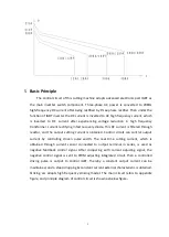
Basic Principle
The control circuit of this cutting machine adopts advanced electronic part IGBT as
the main inverter switch component. Three-phase AC power is converted to 20KHz
high-frequency DC current after being rectified by three phase rectifier. Then under the
function of IGBT inverter the DC current is inverted to AC high frequency current, which
is inverted to DC current after experiencing voltage reduction in high frequency
transformer, current rectifying in fast recovery diode. This DC current is filtered through
reactor, and the output cutting current is obtained. Control circuit can control output
current by controlling driven pulse width. The real time cutting current, which is
obtained through current sensor connected to output terminal in series, is used as
negative feedback control signal. After comparing with current adjusting signal, the
negative control signal is sent to PWM adjusting integrated circuit, then a controlled
driving pulse is output to control IGBT. Thereby a constant output current can be
maintained, and a steep dropping & constant current external characteristic is obtained.
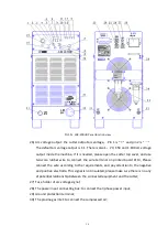
Striking arc adopts high-frequency striking model. The main circuit refers to appendix
figure, and principle diagram of control circuit is shown as below figure
:


