and chain drive sprocket. Refer to
.
• Do maintenance on the cutting equipment regularly
and keep it correctly lubricated. If the saw chain is
not correctly lubricated, the risk of wear on the guide
bar, saw chain and chain drive sprocket increases.
Assembly
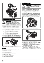
To assemble the impact guard
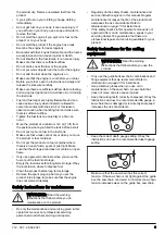
1. Assemble the guard with 3 screws.
2. Tighten the screws to 30 ft/lbs (4 Nm).
3. Tighten the screws again when the product has been
in use for about 20 hours.
To assemble the cutting head
CAUTION:
Make sure that the drive
shaft inside the shaft engages with the cut-
out in the cutting head.
B
A
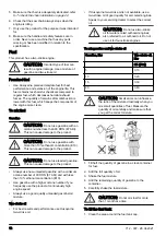
1. Loosen the screw on the cutting head. (A)
2. Fit the cutting head on the shaft so that the screw (A)
is aligned with the hole in the shaft as shown.
3. Finger tighten the screw (A). Make sure that screw
(A) fits into the hole in the shaft.
4. Tighten screw (A).
5. Tighten screw (B).
To assemble the bar and chain
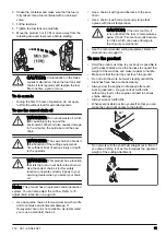
1. Unscrew the bar nut and remove the protective
cover.
2. Fit the bar over the bar bolt. Place the bar in its
rearmost position. Place the chain over the drive
sprocket and in the groove on the bar. Begin on the
top side of the bar.
3. Make sure that the edges of the cutting links are
facing forward on the top edge of the guide bar.
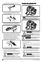
4. Fit the cover and locate the chain adjuster pin (A) in
the hole in the bar. Check that the drive links of the
chain fit correctly on the drive sprocket (B) and that
the chain is in the groove in the bar (C). Tighten the
bar nut finger-tight.
A
B
10
712 - 007 - 28.04.2021
Summary of Contents for 525PT5S
Page 26: ...H00 5 32 in 4 0 mm 85 30 0 025 in 0 65 mm 580 68 74 01 26 712 007 28 04 2021 ...
Page 110: ...H00 5 32 inch 4 0 mm 85 30 0 025 inch 0 65 mm 580 68 74 01 110 712 007 28 04 2021 ...
Page 136: ...H00 5 32 palcev 4 0 mm 85 30 0 025 palcev 0 65 mm 580 68 74 01 136 712 007 28 04 2021 ...
Page 138: ...138 712 007 28 04 2021 ...
Page 139: ...712 007 28 04 2021 139 ...


