background image

9

ASSEMBLY

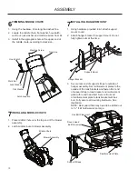
1.  Make sure the tension release lever is forward or 

disengaged.

2.  Place the belt over the pulley on the deck. Refer to 

illustration for proper routing.

3.  Move the tension release arm to the rear and 

engage in the latch.

4

INSTALLING DRIVE BELT

Rear Of Deck

Idler Pulleys

Outer Pulley

Twist in Belt

Tension Release Arm

5

INSTALLING BELT COVERS

1.  Place the deck belt shield on the deck over the 

drive pulley and secure with hardware removed 

from steel belt shield.

2.  Place retainer on the outer pulley cover.
3.  Align the tab end of the belt cover into the slot on 

the deck belt shield and the other end over the end 

of the outer pulley cover.

4.  Secure with knob.

Retainer

Knob

Outer Pulley Cover

Deck Belt Shield

Belt Cover Tab

 Middle Chute Latch

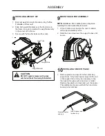
Temporarily secure the hold down bracket to the 

1. 

skid plate, using a bolt and nut from the kit and the 

outer hole in the bracket.


If needed, prop the blower housing up so it sits 

vertically level, but leave no more than an 

1

/

8

" gap 

between the deck and blower housing.  

Skid Plate

Back-up Plate

Back-up Plate

3

INSTALLING HOLD DOWN BRACKET

Using the back-up plate as a template, drill holes 

2. 

in blower housing through the slots on the hold 

down bracket. Drill in the middle of the bracket 

slots to allow for adjustment if needed. Remove 

hold down bracket.
Remove blower housing. Place back-up plate 

3. 

inside the blower housing, lining up new drill holes 

and back-up plate. Install the hold down bracket by 

inserting bolts from the inside, through the blower 

housing and into the bracket slots. Secure with 

flange nuts.

Hold Down 

Bracket

Hold Down 

Bracket Hole

Summary of Contents for 115 149727 R01

Page 1: ...Blower Kit 44 Collection System 966004401 Operator and Parts Manual ...

Page 2: ... 2009 HTC All Rights Reserved Beatrice NE Printed in U S A ...

Page 3: ...rize yourself with the parts before starting the assembly Study the operating instructions and safety precautions thoroughly to insure proper functioning of your Grass Catcher and to prevent injury to yourself and others Save this manual for future reference The operation of any mower can result in foreign objects thrown into the eyes which can result in severe eye damage ALWAYS wear safety glasse...

Page 4: ...ic when operating near or crossing roadways Use extra care when loading and unloading the machine onto a trailer or truck Data indicates that operators age 60 years and above are involved in a large percentage of riding mower related injuries These operators should evaluate their ability to operate the riding mower safely enough to protect themselves and others from serious injury DO NOT operate m...

Page 5: ... with safe machine operation Use extra care when approaching blind corners shrubs trees or other objects that may obscure vision SERVICE The operation of any mower can result in foreign objects thrown into the eyes which can result in severe eye damage Always wear safety glasses or eye shields while operating your mower or performing any adjustments or repairs We recommend a wide vision safety mas...

Page 6: ...wn Frequently check components and replace with manufacturer s recommended parts when necessary Mower blades are sharp and can cut Wrap the blade s or wear gloves and use extra caution when servicing them Check brake operation frequently Adjust and service as shown in the Operator s Manual WARNING DO NOT tow any trailers etc with this mower They may jackknife or over turn causing damage to the mow...

Page 7: ...you are seated on the mower in the operator s position Upper Chute Bag Dump Indicator Blower Housing Middle Chute CONTAINER CONTENTS Blower Assembly Drive Pulley Belt Shield Belt Mounting Bracket Bag of Hardware Weight Belt Cover CAUTION BEFORE ASSEMBLING GRASS CATCHER TO MOWER Set parking brake Place motion control levers in NEUTRAL position Turn ignition key OFF and remove key Make sure the blad...

Page 8: ...rpin cotter supplied with the kit Discharge Chute Reverse rear bolt nut assembly 5 Remove the bolt securing the right hand deck pulley to the spindle 6 Replace right blade shaft with new longer shaft The existing drive pulley and key will fit on the new shaft Install blower drive pulley with the raised portion of pulley hub down Slide spacer inside new pulley Add key to new pulley 7 Remove two rea...

Page 9: ... Deck Belt Shield Belt Cover Tab Middle Chute Latch Temporarily secure the hold down bracket to the 1 skid plate using a bolt and nut from the kit and the outer hole in the bracket If needed prop the blower housing up so it sits vertically level but leave no more than an 1 8 gap between the deck and blower housing Skid Plate Back up Plate Back up Plate 3INSTALLING HOLD DOWN BRACKET Using the back ...

Page 10: ...iddle Chute Blower Assembly Using hardware provided in kit attach support 1 mount to unit Attach hanger bracket to support mount Do not 2 fully tighten nuts at this time Hanger Bracket Secure rear end of support straps to outside of 3 hanger assembly Set reinforcement plates to the outside of the tank brackets and fasten front end of support strap to tank bracket and reinforcment plate with round ...

Page 11: ...using 3 8 16 x 1 bolts and four nuts 2 Slide both weight brackets over the front tube on the frame Be sure to position the weight assembly in the center of the frame 3 Secure with 3 8 16 x 3 bolts and four nuts Front Tube CAUTION DO NOT operate mower with grass catcher without front weight installed NOTE Assistance from another person may ease mounting the cover assembly to mower 1 Lift and rotate...

Page 12: ...he bag draped over upper lip of the Container for replacement bags refer to REPLACEMENT PARTS g Repeat for other container h Reinstall containers making sure right container overlaps left container at center supports i Close cover and secure latches over center support tubes Avoid cutting wet grass or in the morning while the dew is still heavy Grass clippings collected under these conditions tend...

Page 13: ...hazardous projectiles STORAGE When grass catcher is to be stored for a period of time clean it thoroughly remove all dirt grass leaves etc Store in a clean dry place CAUTION Do not leave grass in bagger containers Empty containers after each use and before storing Failure to do so may result in spontaneous combustion which could develop into a fire CAUTION Grass catcher components are subject to w...

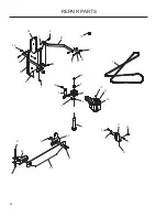
Page 14: ...to 30 ft lbs 15 16 17 18 19 20 21 22 23 39 26 25 29 30 38 28 24 1 2 3 6 10 12 14 47 23 33 34 35 36 31 44 32 37 44 43 11 40 47 48 50 51 52 48 51 53 45 46 27 49 48 41 45 40 15 44 55 11 59 56 11 40 56 11 60 12 REPAIR PARTS 57 54 42 62 61 ...

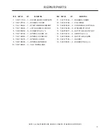
Page 15: ...M PART NO QTY DESCRIPTION ITEM PART NO QTY DESCRIPTION 539 130335 32 1 MOUNT IDLER UPPER 539 130336 33 1 MOUNT IDLER LOWER 539 130337 34 1 ARM IDLER 539 130338 35 1 ARM TENSION 539 130205 36 1 BRacKeT MounT FRONT 522 949902 37 1 BRacKeT MounT REAR 539 130341 38 1 PLATE OUTER 539 130346 39 1 KEEPER 539 200282 40 3 NUT 3 8 16 HEX JAM NYLOC 539 919078 41 1 PULLEY IDLER 539 910935 42 1 washer 539 1155...

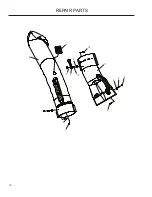
Page 16: ...16 REPAIR PARTS 1 3 7 4 5 8 18 11 14 15 16 10 12 6 2 17 5 17 19 9 13 17 ...

Page 17: ...NG COVER LH 532 132983 7 1 SPRING COVER RH 532 133235 8 1 SPACER COVER 539 108096 9 1 SPRING RETAINER 539 108097 10 3 CAP TUBING END 532 179746 11 1 BAGGER FRAME 532 192786 12 1 PIN HINGE 532 400226 13 2 CONTAINER SOFT BAG 539 105408 14 8 WASHER 10 FLAT 539 976977 15 4 NUT 10 24 HEX NYLOC 539 106312 16 4 HMS 10 24 x 539 108086 17 9 NUT 10 24 ACORN 532 127534 18 1 GASKET 539 108081 19 4 SCREW 10 24...

Page 18: ...18 6 5 4 4 3 3 1 9 2 12 10 7 8 11 REPAIR PARTS ...

Page 19: ... SPACER SPLIT 539 108086 6 2 NUT ACORN 10 24 ITEM PART NO QTY DESCRIPTION ITEM PART NO QTY DESCRIPTION REPAIR PARTS 539 108088 7 1 LATCH HOOD 539 108089 8 1 WELD NUT PLATED 522 739201 9 1 CHUTE UPPER 539 109552 10 2 WASHER 3 16 LOCK 539 130294 11 1 CHUTE MIDDLE 539 976952 12 1 SCREW 10 24 x 625 MACH NOTE ALL FASTENERS ARE GRADE 5 UNLESS OTHERWISE SPECIFIED ...

Page 20: ...20 REPAIR PARTS 1 2 3 4 5 7 8 9 10 11 12 13 14 15 16 17 18 19 20 21 22 23 24 25 26 6 28 29 30 31 32 33 27 1 1 3 3 1 22 24 ...

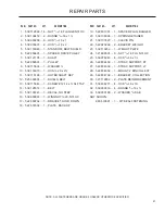
Page 21: ...15 1 DECAL NO STEP 539 990997 16 1 WINGNUT 20 NYLOC 522 860702 17 1 BRACKET HOLD DOWN 522 674502 18 1 PLATE BACK UP 522 801301 19 1 SPACER PLUG BAGGER 539 108096 20 1 SPRING RETAINER 539 107697 21 1 CLEVIS PIN 522 923202 22 2 BRACKET WEIGHT 539 113232 23 1 WEIGHT PLATE 521 996501 24 8 NUT 3 8 16 FLG NYLOC 539 976941 25 4 HCS 3 8 16 x 1 522 854402 26 1 STRAP SUPPORT RT 522 854502 27 1 STRAP SUPPORT...

Page 22: ......

Page 23: ......

Page 24: ...P N 115 149727 R01 05 09 09 ...

Reviews: