WVC
OWNER’S MANUAL & INSTALLATION INSTRUCTIONS
Wireless Valve Controller
Multiple-Station, Battery-Powered Irrigation Controller
Page 1: ...WVC OWNER S MANUAL INSTALLATION INSTRUCTIONS Wireless Valve Controller Multiple Station Battery Powered Irrigation Controller ...
Page 2: ...VC are accomplished with the Wireless Valve Programmer WVP The WVP is a handheld programmer that allows you to create programs and conduct manual operations with WVC controllers in the field Because the WVP retrieves and transmits data via radio signals you never have to open a valve box to check the status or program your controllers http hunter direct wvpwvc 1 800 733 2823 Need more helpful info...
Page 3: ...tching Solenoids to the WVC 7 Radio Communication 8 Addressing the WVC With the WVP 9 Mounting the WVC to a Hunter Valve 10 Alternate Mounting Methods 11 Connecting a Weather Sensor 12 Specifications 12 Operating Specifications 12 Electrical Specifications 12 Dimensions 13 Notices 13 FCC Notice 14 Industry Canada Notice 15 Notes ...
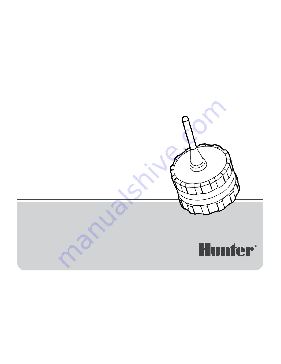
Page 4: ...ttery holder 4 Wires for DC Latching Solenoids Leads are provided for wiring DC latching solenoids The red wires are numbered on top of the WVC to provide station identification The black wire is the common wire 5 Weather Sensor Wires A Hunter Mini Clik or other micro switch type sensor can be connected to the WVC 6 Valve Mounting Clip Allows the WVC to be mounted directly to any Hunter valve The ...
Page 5: ...stance the solenoids are from the controller Under normal service conditions the battery should provide at least one full year of service 3 Make sure no water is inside the battery compartment Make sure that the seals are in good condition Screw the WVC body halves together to seal the compartment Note The battery holder is designed so that the battery can only be inserted in one direction To Inst...
Page 6: ...n from the station wire 2 Remove 13 mm of insulation from the common wire black wire on the WVC 3 Twist the red and black leads from the solenoid to the red and black leads on the WVC as shown in the figure 4 Make sure to use waterproof connectors to secure all wire connections Note The maximum recommended distance from the WVC to any Hunter DC latching solenoid is approximately 100 30 m with 18 g...
Page 7: ...e WVP can send retrieve data to from the WVC up to 100 30 m with the WVC installed in the valve box below ground level Radio range increases when the WVC is installed above ground Refer to the WVP Owner s Manual regarding radio communication WVP WVC Below Ground Installation For maximum radio range position WVC as high as possible see figure below WVP Minimize Clearance Good Not recommended ...
Page 8: ...3 digit identification number Use the button to make sure that the WVP is in the transmit mode with the arrow on the display pointing towards the address icon see Figure 1 3 Unscrew the rear half of the WVC body to gain access to the battery compartment 4 Install a standard 9 volt alkaline battery into the battery holder see Connecting the Battery 5 Wait for the red light inside the battery compar...
Page 9: ...o achieve maximum range for radio communication Figure 2 To Mount the WVC to a Valve Figure 2 1 Unscrew the existing solenoid from the valve 2 Screw the WVC latching solenoid into the valve bonnet 3 Attach the large end of the valve mounting clip to the middle of the WVC body mounting clip supplied with your WVC 4 Snap the small end of the valve mounting clip to the solenoid Note The total length ...
Page 10: ...r is as high up in the valve box as possible but does not interfere with the top of the valve box cover 2 Drive two screws to secure the adapter to the side of the valve box 3 Attach the WVC to the mounting clip and slide it on the end of the mounting adapter Stake Mounting Method Figure 4 The universal mounting adapter can also be used to stake mount the WVC 1 Cut a section of 13 mm diameter plas...
Page 11: ...iddle of the loop 2 Remove approximately 13 mm of insulation from each wire Attach each wire to each of the wires of the weather sensor 3 Secure both wire connections with waterproof connectors Programming the Controller The WVC is simple to program with its companion the WVP Wireless Valve Programmer The easy to understand push button design of the WVP allows you to step through the process of pr...
Page 12: ... delay for 1 to 7 days Specifications Electrical Specifications Selenoids Operates 6 to 9 volt DC latching solenoids Battery Standard 9 volt alkaline battery not included one year minimum life Battery not required for program backup Memory Non volatile for program data weather sensor compatible Frequency of operation 900 MHz ISM band U S Australia 868 MHz Europe Dimensions WVC 3 25 D x 5 H 8 3 cm ...
Page 13: ...erence to radio communications However there is no guarantee that interference will not occur in a particular installation If this equipment does cause harmful interference to radio or television reception which can be determined by turning the equipment off and on the user is encouraged to try to correct the interference by one or more of the following measures Reorient or relocate the receiving ...
Page 14: ...EU with restrictive use for this product are crossed out F D GR IRE I LUX NL P E S UK Industry Canada Notice This notice applies only to models WVC 100 WVC 200 and WVC 400 IC 2772 WVC The term IC before the certification registration number only signifies that the Industry Canada technical specifications were met Operation is subject to the following two conditions 1 this device may not cause inte...
Page 15: ...15 Notes ...
Page 16: ...nd Street San Marcos California 92078 USA www hunterindustries com Helping our customers succeed is what drives us While our passion for innovation and engineering is built into everything we do it is our commitment to exceptional support that we hope will keep you in the Hunter family of customers for years to come Gregory R Hunter CEO of Hunter Industries ...