background image

Commissioning 

OPERATION MANUAL 

Chapter 2 


Unichiller® eo Desktop 


V2.2.0en/09.08.21//17.12 

28 

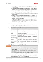
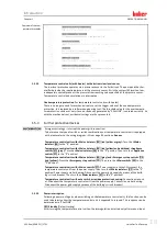
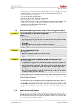
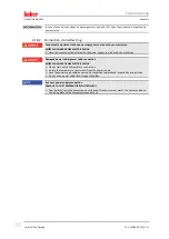
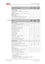
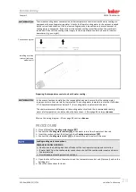
Connection


Sleeve nut wrench 

size


Connector wrench 

size


Recommended 

torques in Nm


Maximum torques 

in Nm


M16x1 

19 

17 

20 

24 

M24x1.5 

27 

27 

47 

56 

M30x1.5 

36 

32 

79 

93 

36 

36 

79 

93 

M38x1.5 

46 

46 

130 

153 

G-thread (flat-

sealing) 

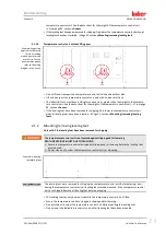
Adapt the torque to the material of the flat seal used. First hand-tighten the temperature 

control hose. 

When using adapters, do not overtighten the G-thread on the pump connection when 

connecting a temperature control hose. When connecting a temperature control hose to 

the adapter piece, secure the G thread against overwinding. 


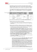
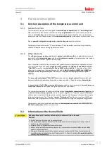
2.7


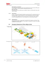
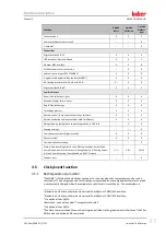
Temperature control units with water cooling 


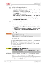
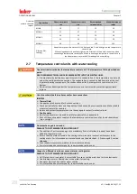
Open electrical wires below the temperature control unit if the temperature falls below the dew 

point. 
DEATH FROM ELECTRICAL SHOCK BY WATER ENTRY INTO THE ELECTRIC LINES. 


A temperature below the dew point may result in condensation in the temperature control unit 

and at the cooling water connections. The condensation is caused by high humidity at the cool-

ing water-bearing components. The condensation exists the temperature control unit at the 

bottom. 


Electrical lines directly below the temperature control unit must be protected against liquid 

ingress. 


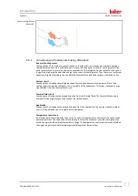
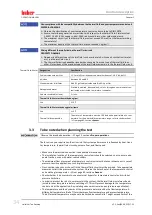
Use of unsuitable/defective hoses and/or hose connections 
INJURIES 


Thermal fluid


Use appropriate hoses and/or hose connections. 


Check periodically for leaks and the quality of the hose and hose connections and take suitable 

measures (replace) as required. 


Isolate and protect temperature control hoses against contact/mechanical load. 


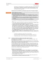
Cooling water


Reinforced hoses must be used to satisfy tougher safety requirements. 


Shut off the cooling water supply to the temperature control unit even for shorter downtimes 

(e.g. overnight). 


No protection against corrosion 
DAMAGE TO THE TEMPERATURE CONTROL UNIT 


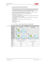
The addition of anti-corrosion agents is mandatory if salts (chlorides, bromide) have been 

added to the water circuit. 


Ensure that the materials used in the cooling water circuit are resistant with respect to the 

cooling water. For information on materials used see the data sheet. 

 From page 85, section 

»Annex«

. 


Take suitable measures to maintain the warranty conditions. 


For information about water quality, see www.huber-online.com. 


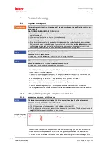
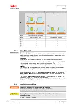
Usage of un-filtered river/sea or ocean water as cooling water 
DAMAGE TO THE TEMPERATURE CONTROL UNIT 


Un-filtered river or sea water is not suitable for use as cooling water due to its contaminants. 


Use drinking water or filtered river or sea water for cooling. 


Sea water must not be used for water cooling. 


For information about water quality, see www.huber-online.com. 


Overview  

wrench sizes and  

torques 

Summary of Contents for Pilot ONE Unichiller 00 eo Series

Page 1: ...Unichiller eo Table Top Models...

Page 2: ......

Page 3: ...OPERATION MANUAL Unichiller eo Table Top Models...

Page 4: ......

Page 5: ...operation manual is a translation of the original operation manual Also for models with heater VALID FOR DESKTOP Unichiller 00x eo Unichiller 01x eo Unichiller 02x eo Abbreviations used in model names...

Page 6: ...OPERATION MANUAL Unichiller eo Desktop V2 2 0en 09 08 21 17 12 6 Pilot ONE Layout of the Home screen...

Page 7: ...its with heater with electronic low level sensor19 1 5 3 Further protective devices 19 1 5 3 1 Power interruption 19 1 5 3 2 Alarm functions 20 1 5 3 3 Warning messages 20 1 6 Exemplary illustrations...

Page 8: ...9 3 8 3 The sub categories 39 3 8 4 The dialogs 39 3 9 Function examples 40 3 9 1 Display of software version 40 3 9 2 Start Stop 40 3 9 3 Copying the settings to a data carrier 41 3 9 3 1 Saving to a...

Page 9: ...externally open applications 61 4 3 2 1 Draining with Sight glass 23 61 4 3 2 2 Draining with Level indicator and drain 38 62 5 Normal operation 63 5 1 Automatic operation 63 5 1 1 Temperature contro...

Page 10: ...n 77 7 4 3 Rinsing the thermal fluid circuit 77 7 4 3 1 Rinsing a thermal fluid circuit with Sight glass 23 78 7 4 3 2 Rinsing the thermal fluid circuit with Level indicator and drain 38 78 7 5 Cleani...

Page 11: ...s listed on page 5 are referred to in this operation manual as temperature control units and Peter Huber K ltemaschinenbau AG as Huber company or Huber Liability for errors and misprints excluded The...

Page 12: ...level List second level 1 2 Information on the EU Declaration of Conformity The equipment complies with the basic health and safety requirements of the European Directives listed below Machinery Dire...

Page 13: ...control unit The following pictograms are used as safety identifiers The table gives an overview of the safety identifiers used here Identifier Description Mandatory sign Observe the instructions War...

Page 14: ...tories and industry Flow through coolers and calibration baths must be used only in com bination with Huber temperature control units Only use thermal fluids suitable for the overall sys tem The cooli...

Page 15: ...r future use e g transport Thermal fluid Please refer to the safety data sheet of the thermal fluid used for information on its proper disposal Use the original thermal fluid container when disposing...

Page 16: ...please refer to the wiring diagram From page 85 section Annex First remove the cover to the air inlet connection an air filter mat is installed behind it This air filter mat must be checked replaced...

Page 17: ...e removed if the exhaust system provided in a building is not used NO gas warning sensor is installed in this temperature control unit Make sure that the installa tion site of the temperature control...

Page 18: ...l before operating the temperature control unit Please observe the safety instructions When operating the temperature control unit wear appropriate personal protective equipment e g safety goggles pro...

Page 19: ...yellow or gray Turn the Mains isolator 36 to the 0 position Temperature control units with Mains isolator 36 red yellow and additional Appliance switch 37 gray Turn the Mains isolator 36 to the 0 posi...

Page 20: ...nfavorable process conditions The temperature control unit can be programmed so that the plant operator is warned when defined limit values are exceeded The response of the temperature control unit to...

Page 21: ...sation temperature Not all the cooling capacity from the coolant circuit is available at the evaporator This means reduced energy transmission from the thermal fluid circuit Thermal fluid circuit Cons...

Page 22: ...e an industrial truck for transport The casters on the temperature control unit are not suitable for transport The casters are sym metrically loaded with 25 of the total mass of the temperature contro...

Page 23: ...eling feet 2 1 2 Mounting removing leveling feet Only valid if the leveling feet have been removed for shipping The temperature control unit is not secured against slipping and or lowering DEATH OR SE...

Page 24: ...or greater than the weight of the tempera ture control unit See the data sheet for the weight of the temperature control unit From page 85 section Annex The leveling feet if present must be unscrewed...

Page 25: ...compliance with the ambient conditions is mandatory Relative humidity max 80 to 32 C and 40 C decreasing linearly to 50 Short distance to supply connections The temperature control unit must not be in...

Page 26: ...protection Design protection measures professional cable selection UV resistance steel pipe protection etc Attention The operating company is responsible for compliance with national international dir...

Page 27: ...s safety footwear Uncontrolled formation of ice at the connections and hoses of the thermal fluid circuit SLIP AND TRIP HAZARD If the temperature is controlled in the minus range ice forms at the hose...

Page 28: ...id ingress Use of unsuitable defective hoses and or hose connections INJURIES Thermal fluid Use appropriate hoses and or hose connections Check periodically for leaks and the quality of the hose and h...

Page 29: ...low 3 C the cooling water supply must be heated The minimum pressure differential in the cooling water circuit and the recommended cooling water inlet temperature can be found on the data sheet From p...

Page 30: ...s the leveling feet from changing their height during operation 2 8 2 Opening closing the bypass valve Some temperature control units are fitted with an adjustable bypass to protect fragile applicatio...

Page 31: ...pplication to the temperature control unit using suitable thermal fluid hoses Observe the table with the wrench sizes Page 27 section Wrench sizes and torques Check the connections for leaks 2 10 Conn...
Page 32: ...e power supply carried out by an electrician Damaged power cable power cable connection MORTAL DANGER FROM ELECTRIC SHOCK Do not start up the temperature control unit Isolate the temperature control u...

Page 33: ...interface 0 4 20 mA or 0 10 V and various digital control options In Out The removable control panel Pilot ONE can also be used as a remote control Please contact your dealer or Huber Sales Departmen...

Page 34: ...tion The mixture s temperature must be 10 K below the permissible min tem perature For the permissible temperature range refer to the datasheet From page 85 section Annex 3 3 To be noted when planning...

Page 35: ...and pressure range The application should be roughly at the same height of or below the temperature control unit if the temperature control process is close to the boiling temperature of the thermal f...

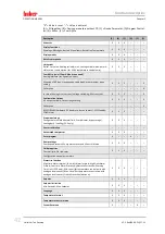
Page 36: ...w level and overtemperature4 X X X Adjustable alarm thresholds X X X VPC5 Variable Pressure Control X X X Ventilation program X X X Automated compressor X X X Setpoint limitation X X X Program control...

Page 37: ...X X Copying settings X Service data recorders flight recorder X X X PB commands6 X X X Communication Watchdog X Process data recording directly to a USB stick Setpoint Actual Value Internal and Actua...

Page 38: ...the menu is reset 2 event types are currently selectable 3 5 2 1 Event function Alarm clock event Several acoustic signals are used 3 5 2 2 Event function Program event After selecting Program event...

Page 39: ...rrow to left Favourites star Add to favorites star with a plus sign Select the Categories menu menu Confirm entry Start stop etc 3 8 2 The categories For clarity we have grouped the Operation and Sett...

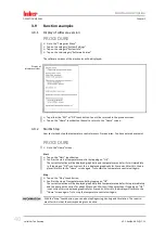
Page 40: ...by tapping on OK The correct selection will be displayed graphically and temperature control will start immediate ly If tapping on OK is not correct this is displayed graphically for 2 seconds After...

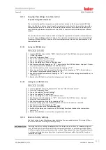
Page 41: ...aved Confirm the entry by tapping on OK Alternatively you can accept the proposed name by tapping on OK Read the message and confirm by tapping on OK The file with the settings was created on the USB...

Page 42: ...onfiguration Output AIF output variable Output range setting X X X X Calibration X RS232 RS485 Hardware RS Baud rate device address ECS Standby POKO Alarm X X X Properties other Change thermal fluid t...

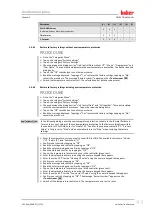
Page 43: ...tores the factory settings tapping on No cancels the procedure In the following dialog enter the overtemperature protection suitable to the thermal fluid used To reset the cut out values of the overte...

Page 44: ...factory settings Page 41 section Restore factory settings After switching on the temperature control unit tap on the required system language Touch OK to confirm your selection Tap on the thermal flu...

Page 45: ...it and interruption The bath or flow temperature is monitored to ensure the safety of your system It is set immediately after you have filled the system with thermal fluid Our temperature control unit...

Page 46: ...ircuit and circulation pump continue to operate In case of an emergency possible exo thermic reaction the full cooling capacity is thus available Please make sure that the automated compressor is set...

Page 47: ...setpoint However damage could result if the temper ature difference limits are exceeded bursting of the application e g glass apparatus This differ ence in temperature may have to be restricted depend...

Page 48: ...nk 4 2 3 Temperature control to process temperature Certain temperature control tasks require that the temperature is recorded elsewhere for best results than described Setting the temperature to proc...

Page 49: ...mit value and the temperature sensor are set properly the load limits e g from a glass appa ratus are not exceeded As the limit value is approached the cooling or heating capacity is adjusted The Delt...

Page 50: ...unction of the controlled system provides you with very quick and reliable adapted control parameters These control parameters achieve a fast and very accurate tuning performance The more complex but...

Page 51: ...tpoints and automatically processes them one after another One of these is below room temperature one roughly at room temperature and one above room temperature if the setpoint limits allow this PROCE...

Page 52: ...a possible and accepted small tempera ture overshoot and a tuning performance without temperature overshoot The default setting is Fast small overshoot The overshoot always refers to the leading temp...

Page 53: ...ry TAC Manual Tap on the sub category Configuration auto Tap on the sub category Fluid Properties Tap on the sub category Select Fluid Select the thermal fluid used from the list Confirm your choice b...

Page 54: ...ategory Temperature Control Tap on the category TAC Manual Tap on the sub category Configuration auto Tap on the sub category Display parameters Tap on OK after you have read checked the parameters 4...

Page 55: ...Go to the Categories Menu Tap on the category Temperature Control Tap on the category TAC Manual Tap on the sub category Configuration manual Tap on the sub category Change parameters Tap on the sub...

Page 56: ...tructure Choose between the dialogue entries Huber PID controller and Classic PID controller Confirm your choice by tapping on OK 4 2 10 Sub category Reset parameters With this function you can reset...

Page 57: ...rect it will be displayed graphically for 2 seconds The dis play will then return to the category Setpoint Limits Try changing the Min Setpoint again Tap on the sub category Maximum Setpoint Enter the...

Page 58: ...y data sheet for the thermal fluid to be used INJURIES Risk of injury to the eyes skin respiratory tract The safety data sheet for the thermal fluid to be used must be read prior to using it and its c...

Page 59: ...om forming in the Sight glass 23 No thermal fluid may leak from the Sight glass 23 when fill ing Slowly fill suitable thermal fluid into the open application The thermal fluid flows via the Circu lati...

Page 60: ...nt thermal fluid Adjust the pressure in the thermal fluid circuit for temperature control units with Bypass valve 62 to the external application used To do this use the Bypass valve 62 and the pressur...

Page 61: ...e for sufficient thermal fluid Stop venting To do this go to the category Temperature Control Tap on the category Start Stop Tap on the dialog entry Stop air purge Confirm your choice by tapping on OK...

Page 62: ...Circulation return 2 Leave the temperature control unit open for a while to allow it to dry out and the residue to drain Close the connection Circulation flow 1 Close the connection Circulation retur...

Page 63: ...tapping on OK is not correct this is displayed graphically for 2 seconds After this the dis play will return to the Home screen again Try to start the temperature control unit again 5 1 1 2 Ending the...

Page 64: ...uid up to room temperature using the temperature control unit Do not close the shut off valves in the thermal fluid circuit You can either end the temperature control automatically using the parameter...

Page 65: ...is a fast and flexible interface Standard 10 100 Mbps interface Fast Ethernet can be connect ed to any existing Ethernet network Because this interface can also be connected to very large networks the...

Page 66: ...faces at the temperature control unit during operation DAMAGE TO THE INTERFACES When devices in operation are connected with interfaces of the temperature control unit interfaces may get damaged Befor...

Page 67: ...tical thresholds for the temperature control fluid must be strictly observed The control results contained in the data sheet can only be achieved with shielded sensor leads We recommend the external P...

Page 68: ...the category Interfaces The potential free contact PoKo signals the state of the temperature control unit via the contact position A closed operating contact means readiness for operation If a fault o...

Page 69: ...synchro nous This mode is useful if a Unipump is to be monitored either to guarantee the desired circu lation or to prevent an unintended heating of the thermal fluid Programmer This activates the ind...

Page 70: ...nge from a closed to an open contact replaces the set setpoint with the value of the second setpoint This altered setpoint is not fixed to the second setpoint but can be changed by the operator at the...

Page 71: ...oo low For this purpose a level sensor must be connected and placed in the sight glass 23 or in the external application The interface is specified as a digital input Do not apply voltage or current P...

Page 72: ...ure control unit from the power supply In case of fault you can replace the Pilot ONE yourself If you have questions or difficulties please contact your dealer your local office or our Customer Suppor...

Page 73: ...irective Page 17 section Temperature control units with fluorinated greenhouse gases refrigerants Operating company A W Check the power supply cable Prior to switching on the tempera ture control unit...

Page 74: ...in normal mode 7 3 2 2 Replacing coolant hoses PROCEDURE Drain the cooling water Page 82 section Draining the cooling water Replace the defective coolant hoses Follow the instructions for the proper...

Page 75: ...ally open applications Tilt the temperature control unit to remove the grille if available in front of the liquefier fins Clean the liquefier fins using suitable cleaning appliances Observe the local...

Page 76: ...the collecting containers below the Cooling water inlet 13 and below the Cooling water drain 15 if present Dispose of the contents of the collecting containers Follow the in structions for the proper...

Page 77: ...g from one type of thermal fluid to an other No residues of the previous type of thermal fluid may remain in the thermal fluid circuit 7 4 2 1 Externally open application Observe the following when re...

Page 78: ...Start temperature control Touch OK to confirm your selection The length of rinsing depends on the level of soiling Tap on the category Start Stop Tap on the dialog entry Stop temperature control Touch...

Page 79: ...lling and venting with Level indicator and drain 38 Restart the temperature control unit in normal mode 7 5 Cleaning the surfaces Extremely hot cold surfaces connections and thermal fluids BURNS FREEZ...

Page 80: ...HE TEMPERATURE CONTROL UNIT Carry out appropriate decontamination The decontamination process depends on the type and quantity of the materials used Consult the relevant safety data sheet You will fin...

Page 81: ...al fluid to be used must be read prior to using it and its content must be respected Observe the local regulations work instructions Wear your personal protective equipment e g temperature resistant s...

Page 82: ...d on the building side Place a collecting container below the cooling water outlet 13 14 and 15 Open the Cooling water drain 15 and disconnect the Cooling water outlet 14 from the water return The coo...

Page 83: ...l requirements in this section to avoid damage to the temperature control unit Transport using the lugs if fitted on the top of the temperature control unit Do not transport the temperature control un...

Page 84: ...ss brass nickel plated brass and silver solder Proper recycling of the temperature control unit and accessories can actively help reduce CO2 emissions in the production of these materials Follow the l...

Page 85: ...Annex Chapter 9 OPERATION MANUAL V2 2 0en 09 08 21 17 12 Unichiller eo Desktop 85 9 Annex...

Page 86: ...u es Kullan m talimat Betriebsanleitung Operation manual Manual de instrucciones Manueld utilisation Manualeded uso Manual de instru es Kullan m talimat Inspired by temperature Inspired by temperature...

Reviews: