


System Configuration __________________________________________________________________
RF-MCGARDPRO
Hubbell Power Systems, Inc.
–
RFL™
Products
July 1, 2022
©2022 Hubbell Incorporated
4-21
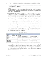
4.9.3 Setting Switches on the Relay Output Unit
The relay output can be changed as shown below.
SW1
SW2
SW3
SW4
SW5
SW6
K1
K2
K3
K4
K5
K6
A
B
A
A
A
B
B
B
B
B
A
A
Slide the switch to move
from Form A (normally
open) to Form B
(normally closed)
F
O
R
M
A
F
O
R
M
B
SW
1
Switch Setting (typical)
Slider Switches
Figure 4-21. Setting Switches on the Relay Output Unit
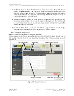
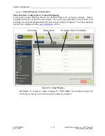
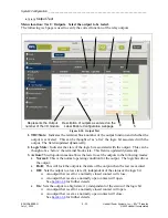
4.9.4 Input/Output Module Status, Configuration and Test
Solid-state outputs, relay outputs and input modules are equipped in sets of 6, with 2 modules on
each base board occupying 1 slot. Ten rear slots are available in the 6U version and 4 rear slots
are available in the 3U version Inputs and outputs may have a system logic timer associated with
them that has settings for both pick-up delay and drop-out delay. When configuring inputs and
outputs, slots that are populated will show in the side-bar menu. Select which slot you wish to
configure.
Note:


