Installation __________________________________________________________________________
RF-MCGARDPRO
Hubbell Power Systems, Inc.
–
RFL™
Products
July 1, 2022
©2022 Hubbell Incorporated
3-16
3.6
Rear I/O, Alarm Relay and Input Power Connections
3.6.1 Rear I/O Terminal Block Connections
The terminal blocks on the rear of the HPS/RFL GARD Pro system chassis are conventional
screw-type barrier blocks. Wires can either be stripped or terminated in spade lugs, depending
on local practice. HPS/RFL recommends that wires be terminated by #6 ring lugs as an extra
safety precaution.
1
2
3
4
5
6
7
8
9
1
0
1
1
1
2
1
3
1
4
1
5
1
6
1
7
1
8
1
9
2
0
2
1
2
2
2
3
2
4
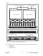
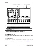
Typical terminal block with six
inputs and six relay outputs
Out 2
Out 1
Out 3
In 2
In 1
In 3
In 4
In 5
In 6
Out 4
Out 5
Out 6
Output
Input
Figure 3-12. Rear I/O Terminal Block Connections
Note
:
I/O positions can be switched or can be all outputs or all inputs. Consult the chassis drawing
referenced in
3.6.2 Alarm and Alert Relay Connections
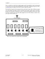
The HPS/RFL GARD Pro system chassis has two SPDT (Form C) relays mounted in the Power
Supply I/O module. The terminals are labeled as shown on the following page. The Major Alarm
relay terminals are on the left of the figure and the Minor Alarm relay terminals are on the right.
The contacts are rated 100mA, 300Vdc, resistive load. The alarm relays will respond to alarm
and alert conditions. The functionality can be customized by the user as required.


