Troubleshooting ______________________________________________________________________
RF-MCGARDPRO
Hubbell Power Systems, Inc.
–
RFL™
Products
July 1, 2022
©2022 Hubbell Incorporated
8-7
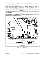
CAUTION
The following table lists test points designed for factory use only. These points are not ESD
protected. Users should not need to connect test equipment to these points in the field.
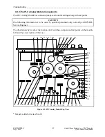
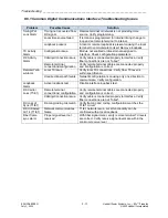
Table 8-4 Settings for the PLC Digital Board
Reference
Designation
Description
Function
DS1
LED Indicator
Green = Enabled
Amber = Disabled
– Module (Main Board)
Red = TX Disabled
DS2
LED Indicator
Green = No Alarms
Red = Any Alarm(s)
DS3
LED Indicator
Green = TX Shift Up
DS4
LED Indicator
Green = RX Shift Up
DS5
LED Indicator
Green = TX Center
DS6
LED Indicator
Green = RX Center
DS7
LED Indicator
Green = TX Shift Down
DS8
LED Indicator
Green = RX Shift Down
J3
4-pin Header
Debug Header: For factory use only.
J4
8-pin Header
For factory use only.
J5
8-pin Header
For factory use only.
J8
7-pin Header
PIC Programming Header: For factory use only.
J9
26-pin Header
Actel Programming Header: For factory use only.
J10
3-pin Header
NORM: Must always be in NORM position
TEST: For factory use only.
J11
14-pin Header
For factory use only.
J12
3-pin Header
NORM: Must always be in NORM position
DEBUG: For factory use only.
J13
6-pin Header
Flash Programming Header: For factory use only.
J14
3-pin Header
DSP: For factory use only.
J15
3-pin Header
MPU: For factory use only.
J16
3-pin Header
NORM: Must always be in NORM position
PRGM: For factory use only.
SW1
Push Button Switch
For factory use only.
TP1
Test Point
For factory use only.
TP2
Test Point
For factory use only.
TP3
Front Panel Test
Point
Line Out: In 4W Mode: TX output to line
In 2W Mode: TX/RX line connection
TP4
Test Point
+15V: +15V Analog Supply
TP6
Test Point
+5VA: +5V Analog supply
TP7
Test Point
+2.5V: +2.5V Digital supply
TP8
Test Point
GND: Ground
Continued….


