


Digital Communications Interfaces ________________________________________________________
RF-MCGARDPRO
Hubbell Power Systems, Inc.
–
RFL™
Products
July 1, 2022
©2022 Hubbell Incorporated
7-38
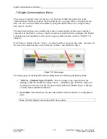
7.5.7 Status Timeslot bus for Digital Comms
This page allows the user to view the status of different parameters of the Timeslot bus comms.
This page displays the status of the GARD Internal Comms Bus (one tab for Bus 1, one tab for
Bus 2). It shows function/interface mapping for each timeslot, and it shows the status of each
function/interface if applicable. The page updates dynamically.
1
2
3
4
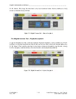
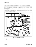
Figure 7-26. Status Screen Timeslot bus Digital Comms
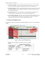
Interfaces which are mapped to more than one timeslot will overlap the timeslot. See Slot 2 –
C37.94 in the example: it’s one continuous block, not 3 individual blocks, covering the range
TS1-TS3.
Note
: Clicking on a function or interface which has a Status page associated with it will take
the user to that Status page.
Each comms bus has a “bus master” or timing master, which provides the timing to the bus.
The Bus Master, if there is one (bus isn’t empty), is shown in the upper-right hand corner. The
Bus Master’s timing mode is also shown (internal / loop).
Descriptions apply to both Bus 1 and Bus 2 tabs.
1.
Master
: Shows the location, type, and timing mode of the Bus Master.
2.
Function column
: Any module which is mapped as a function on this Bus is shown
here, in its timeslot, and its status is shown as gray/green/amber/red.
Clicking the block will take the user to the associated status page
3.
timeslot column
: Shows the timeslot numbers from 1-12


