


Digital Communications Interfaces ________________________________________________________
RF-MCGARDPRO
Hubbell Power Systems, Inc.
–
RFL™
Products
July 1, 2022
©2022 Hubbell Incorporated
7-36
Note
: Reset the following counters to zero by the “Reset All” button.
14.
Errored Seconds
: Provides a count of the total number of errored seconds since the last
reset.
15.
Errors per Second:
Provides a count of the number of errored words that occurred over
the last second.
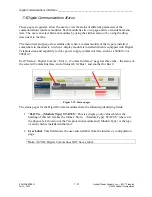
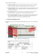
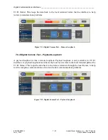
7.5.6 Status Async Digital Comms
This page allows the user to view the status of different parameters of the Async comms interface
module.
1
2
10
3
4
5
6
7
8
9
STATUS > Digital Comms > Slot # - Async
Figure 7-25. Status Screen Async Digital Comms
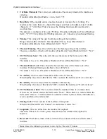
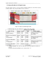
1.
Major Alarm
: This is alarm status from the module. It is global and applies to both
Channel 1 and Channel 2. Indicates whether the module is in major alarm or not. Text
will also explain the possible error detected. The following table lists all the possible
results.
Result
Explanation
Inactive
No Major Alarm.
CHAN1 CONFIG BAD
Channel 1 configuration is bad. Check that the start bit and Baud Rate
setting don't cause the bits to overflow into the next timeslot.
CHAN2 CONFIG BAD
Channel 2 configuration is bad. Check that the start bit and Baud Rate
setting don't cause the bits to overflow into the next timeslot.
CHAN1 AND CHAN2
CONFIG
Same as above, but both channels 1 and 2 have configuration
OVERLAPPING BITS
USED CHECK CONFIG
The bits channel 1 would use overlap those of channel 2. Check the
configuration.
BAD COMMS BUS IN
USE
One of the channels is configured to transmit receive to/from a comms
bus that this async module cannot detect a valid clock on


