


20
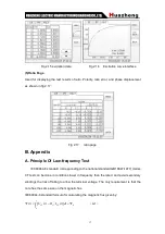
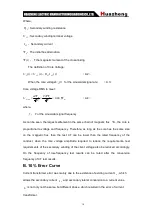
Based on the above formula, the final could be a multiple
M
of the maximum
short-circuit current and burden impedance
B
Z
of the maximum allowable 10% error
described curve (see Figure 2.12).
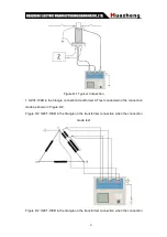
C. Actual Connection Method
HZCT-100B for the CT test the basic connection steps (see Figure D.1) as follows:
(1) 4mm2 line the left side of HZCT-100B is connected to the grounding terminal
protected.
(2) To connect a CT primary side and secondary side terminals of a terminal to protected
areas.
(3) To ensure that all the CT terminal of the other transmission lines disconnect from, all
other windings open.
(4) 2.5mm2 red and black line CT secondary side connected to the HZCT-100B "Output"
K1 and K2 jack, the yellow line and 2.5mm2 line CT secondary side connected to the
HZCT-100B "Sec" jack of the S1 and S2, the attention of even the two black lines in the
CT secondary side has received the same protection to terminal.
(5) Green Line and 2.5mm2 lines CT is connected to a side of HZCT-100B 's "Prim" of P1
and P2 terminal, P2 and CT through the black line is connected to the protection of one
side of the terminal connected.
(6) No problems in check wiring, to begin testing.


