


3
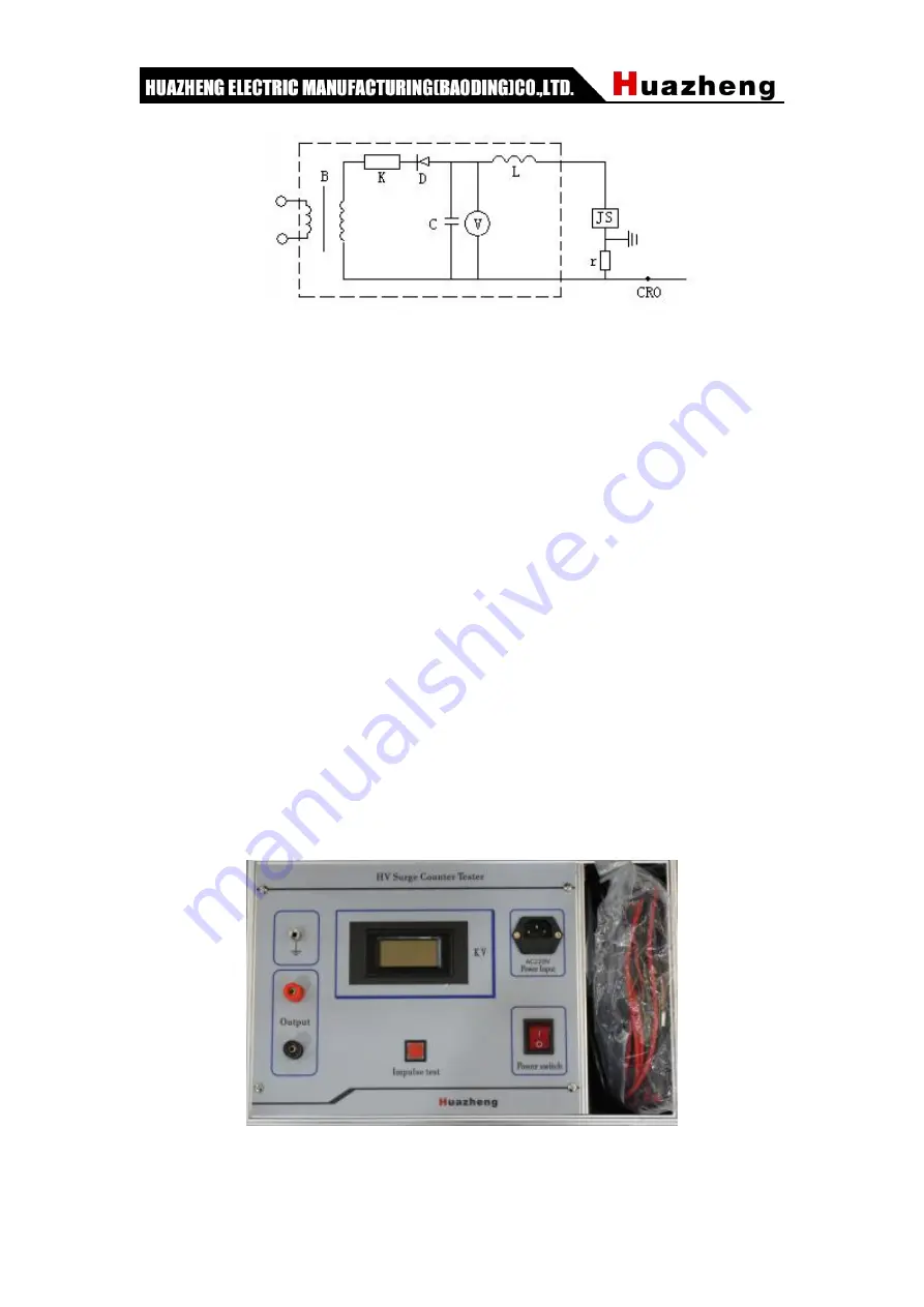
Fig. 2 principle wiring of standard impulse current detection method
(
The part of the dotted box is an impulse current generator
)
C-Charge capacitance
;
R-Charging resistance
;
L-Damped inductor
D-Silicon diode rectifier
;
r-Shunt
;
B-Testing transformer
V-Electrostatic voltmeter
;
CRO-High voltage oscilloscope
If the impulse current wave of 8/20s and 100A produced by the impulse current
generator acts on the action recorder, if the action of the recorder is normal, the
instrument is good, otherwise it should be dismantled and repaired. For example, a power
bureau has used this method to detect 27 counting devices, of which 3 are not moving,
and the internal components are found damped and damaged after disintegration.
The Regulations stipulate that continuous testing should be carried out 3 to 5 times,
each time should be normal, and each time interval should be no less than 30 seconds.
After testing, the recorder should be adjusted to 0.
V.Operation Method
Fig. 3 Schematic diagram of detector panel
1. Connect the output end of the instrument with both ends of the arrester counter


