background image

FusionModule800 Smart Small Data Center 
Installation Guide (Six Fans) 

4 Cable Routing 


Issue 10 (2019-12-20) 

Copyright © Huawei Technologies Co., Ltd. 

199 


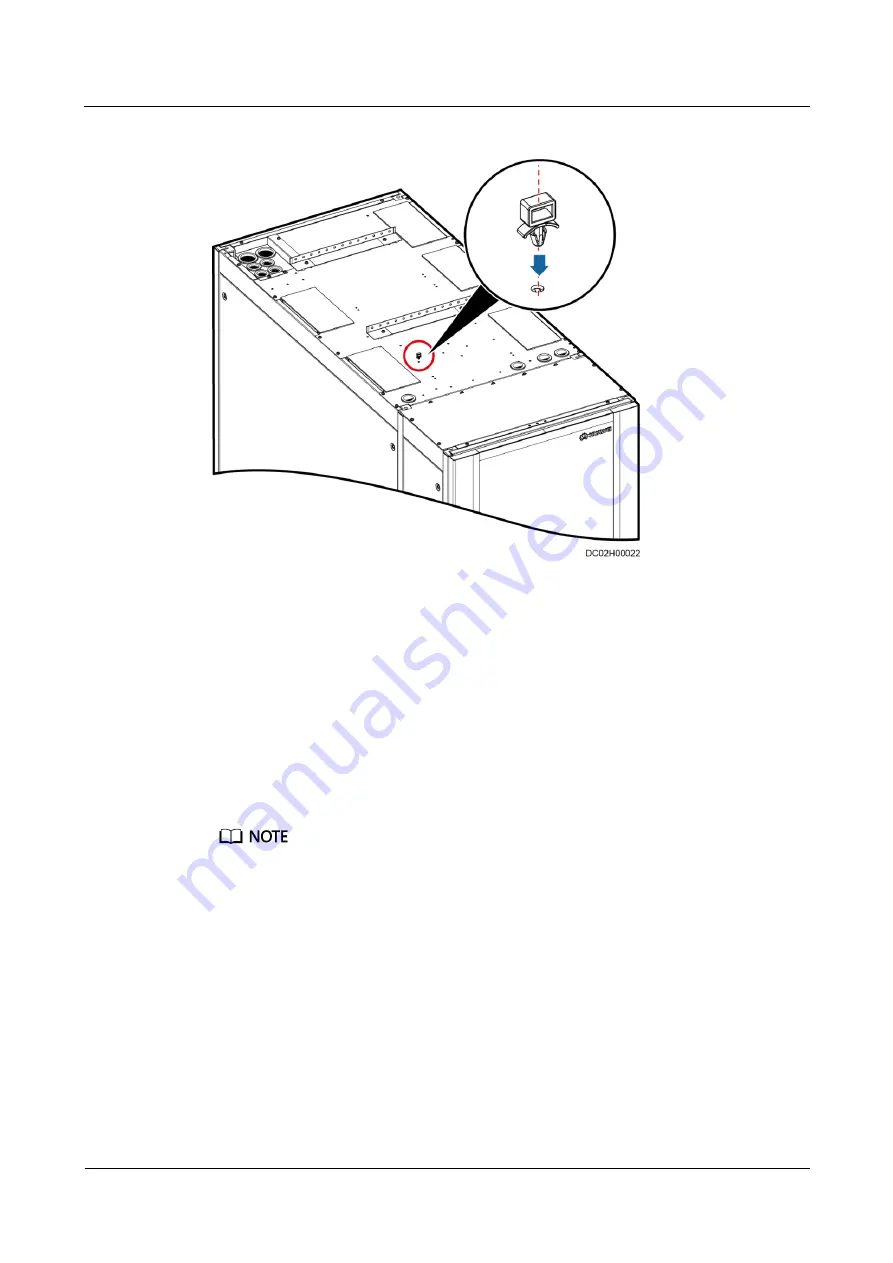
Figure 4-10


Installing a plastic cable tie 


Emergency Fan Cable Route 

The emergency fan components are installed at the top of the aisle containment by default. 
The emergency fan power cable needs to be connected onsite, as shown i

Figure 4-12

. 

1.


Remove the cover from the XT7 terminal block at the rear door of the Converged 
Cabinet, as shown i

Figure 4-11

. 

2.


Connect the fan components in series using the delivered cables. 

3.


Connect the cables delivered with fan components from the power ports on the two 
outermost fan components of the Smart Module to the XT7 terminal block at the rear 
door of the Converged Cabinet. 


Connect cables based on the cable labels and silk screens on the XT7 terminal block. 


The XT7–5 and XT7–7 terminals on the XT7 terminal block are 48 V (+) ports, and the XT7–6 and 
XT7–8 terminals are 48 V (–) ports. 

Summary of Contents for FusionModule800

Page 1: ...FusionModule800 Smart Small Data Center V100R001 Installation Guide Six Fans Issue 10 Date 2019 12 20 HUAWEI TECHNOLOGIES CO LTD ...

Page 2: ...tomer All or part of the products services and features described in this document may not be within the purchase scope or the usage scope Unless otherwise specified in the contract all statements information and recommendations in this document are provided AS IS without warranties guarantees or representations of any kind either express or implied The information in this document is subject to c...

Page 3: ...ed for Hardware installation engineers Commissioning engineers Maintenance engineers Technical support engineers Symbol Conventions The symbols that may be found in this document are defined as follows Symbol Description Indicates a hazard with a high level of risk which if not avoided will result in death or serious injury Indicates a hazard with a medium level of risk which if not avoided could ...

Page 4: ...the manual name and so on Issue 07 2018 09 26 Replaced the PDU2000 02120837 with 02120837 009 Deleted the description related to the BOM number of the 04151747 cable Issue 06 2018 08 05 Added VCN540 and changed VCN500 to VCN Connect the VCN cable to the PoE_1 port on the smart ETH gateway Modified the section Commission the CIM and Battery Interface Module BIM Issue 05 2017 12 15 This issue is the...

Page 5: ...nts Added methods for installing and commissioning the in room access control system Added the VCN500 commissioning guide Added the LAN switch installation method Optimized the monitoring cable wiring diagram Optimized the cable list Issue 02 2016 11 15 This is the second official release Optimized safety precautions Optimized the description about the camera support water sensor mechanical part a...

Page 6: ...allation Scenarios 21 2 5 Smart Cooling Product Installation 24 2 6 Personnel Requirements 25 3 Hardware Installation 26 3 1 Transportation and Unpacking 26 3 1 1 Cabinet Transportation and Unpacking 26 3 1 2 Smart Cooling Product Transportation and Unpacking 30 3 2 Optional Removing Aisle Containments 33 3 3 Adjusting the Positions of Aisle Side Sealing Plates 40 3 4 Adjusting the Positions of Ca...

Page 7: ...onitoring Devices 121 3 11 1 Installing the SIM Card and Antenna 121 3 11 2 Installing a PAD 122 3 11 3 Optional Installing a VCN500 126 3 11 4 Installing the VCN540 128 3 11 5 Optional Installing a LAN Switch 131 3 11 6 Installing T H Sensors in Cold Aisle Containments 133 3 11 7 Installing T H Sensors in Hot Aisle Containments 147 3 11 8 Installing a Camera 158 3 11 9 Installing a Smart ETH Gate...

Page 8: ... Cable to the Smart ETH Gateway 222 4 6 5 Connecting a Monitoring Cable to the AI DI Module 223 4 6 6 Connecting the Smoke Detector Monitoring Cable 224 4 6 7 Connecting Cables to Water Sensors 225 4 6 8 Optional Connecting Cables for the In Room Access Control System 226 5 Checking After Installation 228 6 Power On Commissioning 232 6 1 Power On Commissioning for the ATS 232 6 2 Power On Commissi...

Page 9: ...gured 258 6 3 10 3 Setting Parameters on the VCN WebUI 261 6 3 10 4 Setting Parameters on the VCN IVS Client 263 6 4 Power On Commissioning for the Cooling System 265 6 4 1 Equipment Power On 265 6 4 2 Initial Configuration 266 6 4 2 1 Setting Temperature and Humidity 266 6 4 2 2 Setting Teamwork Control Parameters 267 6 4 2 3 Setting Max Speed of Indoor Fan 269 6 4 3 Commissioning 269 A Appendix ...

Page 10: ...perating or maintaining the equipment The safety instructions in this document are only supplements to local laws and regulations Huawei will not be liable for any consequences of the following circumstances Operation beyond the conditions specified in this document Installation or use in environments which are not specified in relevant international or national standards Unauthorized modification...

Page 11: ...a conductor surface or terminal measure the contact point voltage and ensure that there is no risk of electric shock After installing the equipment remove idle packing materials such as cartons foam plastics and cable ties from the equipment area In the case of a fire immediately leave the building or the equipment area and turn on the fire alarm bell or make an emergency call Do not enter the bui...

Page 12: ... with scratches cannot be exposed to an outdoor environment for a long period of time Before operations ensure that the equipment is firmly secured to the floor or other solid objects such as a wall or an installation rack Do not use water to clean electrical components inside or outside of a cabinet Do not change the structure or installation sequence of equipment without permission Do not touch ...

Page 13: ...d are clear of the sources and degree of various potential hazards in equipment installation operation maintenance Trained personnel personnel who are technically trained have required experience are aware of possible hazards on themselves in certain operations and are able to take protective measures to minimize the hazards on themselves and other people Operators operation personnel who may come...

Page 14: ... cables ensure that a distance of at least 30 mm exists between the cables and heat generating components or areas This prevents damage to the insulation layer of the cables Do not route cables behind the air intake and exhaust vents of the equipment Ensure that cables meet the VW 1 flame spread rating requirements Bind cables of the same type together When routing cables of different types ensure...

Page 15: ...ironment Requirements To prevent fire due to high temperature ensure that the ventilation vents or heat dissipation system are not blocked when the equipment is running Install the equipment in an area far away from liquids Do not install it under areas prone to condensation such as under water pipes and air exhaust vents or areas prone to water leakage such as air conditioner vents ventilation ve...

Page 16: ...rn away irrelevant personnel Carry the operation machinery and tools properly to prevent them from falling off and causing injuries Personnel involving working at heights are not allowed to throw objects from the height to the ground or vice versa Objects should be transported by tough slings hanging baskets highline trolleys or cranes Ensure that guard rails and warning signs are set at the edges...

Page 17: ...t it is intact and confirm its load bearing capacity Do not overload it Ensure that the ladder is securely positioned The recommended angle for a ladder against the floor is 75 degrees as shown in the following figure An angle rule can be used to measure the angle Ensure that the wider end of the ladder is at the bottom or protective measures have been taken at the bottom to prevent the ladder fro...

Page 18: ...aware of unstable or heavy objects on the cabinet Be cautious to avoid injury when moving heavy objects When moving the equipment by hand wear protective gloves to prevent injuries Move or lift the equipment by holding its handles or lower edges Do not hold the handles of modules such as power supply units fans and boards that are installed in the equipment because they cannot support the weight o...

Page 19: ...r to prevent scalds When maintaining or replacing components pay attention to high pressure components such as the compressor and refrigerant pipe to prevent the refrigerant system from being cracked or exploded due to misoperations Refrigerant Frostbite Refrigerant leakage may cause frostbite Take protective measures for example wear antifreeze gloves when handling refrigerant Storage and Recycli...

Page 20: ... wash it immediately with clean water and go to the hospital for medical treatment Use dedicated insulated tools Move batteries in the required direction Do not place a battery upside down or tilt it Keep the battery loop disconnected during installation and maintenance Use batteries of specified models Using batteries of other models may damage the batteries Dispose of waste batteries in accordan...

Page 21: ...ot use unsealed lead acid batteries To prevent fire or corrosion ensure that flammable gas such as hydrogen is properly exhausted for lead acid batteries Lead acid batteries emit flammable gas when used Ensure that batteries are kept in a well ventilated area and take preventive measures against fire Battery Leakage Battery overheating causes deformation damage and electrolyte spillage When the el...

Page 22: ...ature charging is forbidden at 0 C Low temperature charging may cause crystallization which will result in a short circuit inside the battery Use batteries within the allowed temperature range otherwise the battery performance and safety will be compromised Do not throw a lithium battery in fire When maintenance is complete return the waste lithium battery to the maintenance office 1 8 Others Exer...

Page 23: ...ments Prepare the tools and meters required for installation Table 2 1 General tools and instruments Name Specifications and Appearance Protective gloves Marker Measuring tape 5 m Level Step ladder 2 m Phillips screwdriver M4 M6 and M8 Flat head screwdriver 2 5 mm Torque wrench Adjustable wrench 6 Socket wrench M6 M8 and M12 Hex key 5 mm Laser locator Right angle Electrician s knife Impact tool He...

Page 24: ... pliers Diagonal pliers RJ11 crimping tool Polyvinyl chloride PVC insulation tape Wire stripper Hydraulic pliers Wire clippers Crimping tool Multimeter Electroprobe Heat shrink tubing Cable ties Hammer drill Electric screwdriver Rubber mallet N A N A Table 2 2 Tools and instruments for installing smart cooling products Name Specifications and Appearance Flashlight Hacksaw Pallet truck Electric bal...

Page 25: ...um pumpd Water pipe thread sealante a Pressure gauge and leather hose dedicated to R410A pressure gauge measurement range 4 0 MPa and the leather hose tolerance range 4 5 MPa The size of needle valve in the unit is 1 4 inch Purchase a conversion adapter if you have a different size of valve on leather hoses b Dry nitrogen c Nitrogen reducing valve A reducing valve must be installed on the head of ...

Page 26: ...ion Table 2 3 Installation environment checklist Check Item Specifications Check Result Bearing capacity Standard live load of the main equipment room 8 12 kN m2 If the battery cabinet is placed inside the module use the standard live load of the main equipment room as a reference Suspended load of the main equipment room 1 2 kN m2 Standard live load of the battery room 16 kN m2 Passed Failed Leve...

Page 27: ...ts to external water pipes to supply water to the humidifier Passed Failed If any of the requirements is not met contact Huawei technical support The UPS can generate large leakage currents A circuit breaker equipped with an RCD is not recommended If leakage protection is required select a recommended upstream circuit breaker for the smart module Table 2 4 Recommended circuit breaker NetCol500 A01...

Page 28: ...roducts One Cooling Only Smart Cooling Product One Smart Cooling Product with Heating and Humidif ication Two Smart Cooling Products with Heating and Humidif ication Three Smart Cooling Products Term inal Speci ficati ons Resid ual Curre nt Circu it Brea ker specifica tions Input power cable specifica tions 5 x 16 mm2 5 x 16 mm2 5 x 16 mm2 5 x 16 mm2 5 x 16 mm2 M6 OT termin al 15 kW Circuit breake...

Page 29: ...cts Term inal Speci ficati ons Resid ual Curre nt Circu it Brea ker 6 kW Circuit breaker specifica tions C80 3P C80 3P C100 3P C100 3P C125 3P 100 mA Input power cable specifica tions 5 x 16 mm2 5 x 16 mm2 5 x 16 mm2 5 x 16 mm2 5 x 16 mm2 M6 OT termin al 12 kW Circuit breaker specifica tions C80 3P C100 3P C100 3P C100 3P 300 mA Input power cable specifica tions 5 x 25 mm2 5 x 25 mm2 5 x 25 mm2 5 ...

Page 30: ...T cabinet 2000 mm x 600 mm x 1350 mm 160 kg Converged Cabinet 2000 mm x 600 mm x 1350 mm 410 kg Battery cabinet deployed inside the aisle containment 2000 mm x 600 mm x 1350 mm 160 kg Battery cabinet deployed outside the aisle containment 2000 mm x 600 mm x 1100 mm or 1200 mm 140 kg Network cabinet 2000 mm x 600 mm x 1350 mm 160 kg Cabinets and aisle containments are assembled for delivery The cab...

Page 31: ...yright Huawei Technologies Co Ltd 22 Figure 2 2 Component layout 1 Binding plate 2 Cabinet sealing plate 3 IT cabinet 4 Converged Cabinet 5 Battery cabinet 6 PAD 7 Camera The IT cabinet to the left of the Converged Cabinet houses various components depending on the configurations Figure 2 3 shows the recommended layout ...

Page 32: ...abinets and PDU2000s based on Figure 2 4 The following describes how to number cabinets and PDU2000s in a scenario with five cabinets 1 2 and 3 refer to the cabinet number and A and B refer to the PDU2000 number You are advised to number cabinets from left to right The battery cabinet and Converged Cabinet do not have to be numbered PDU2000s are deployed at the cabinet rear door and are recommende...

Page 33: ...ensions Smart cooling product outdoor units are available in two models NetCol500 A018 and NetCol500 A020 Figure 2 5 and Figure 2 6 show the dimensions of NetCol500 A018 and NetCol500 A020 NetCol500 A018 and NetCol500 A020 are installed in the same way This manual uses figures of NetCol500 A018 as examples Figure 2 5 Installation dimensions of NetCol500 A018 Figure 2 6 Installation dimensions of N...

Page 34: ... understand basic safety precautions are allowed to install and operate a modular data center Huawei will not be liable for any consequence caused by the violation of this document The requirements are as follows Customers installation personnel must be trained by Huawei and understand how to install and operate a modular data center The number of installation personnel varies based on the project...

Page 35: ...lation position unpack it and take care to prevent scratches Keep the cabinet steady during unpacking If the cabinet installation environment is in poor condition to well store the cabinet after it is unpacked take measures to prevent dust You can wrap the cabinet with the original plastic coat Do not tear down the transparent film from the glass door during the installation The film will be remov...

Page 36: ...d the information and contact your local Huawei office immediately 4 After checking that the cabinet is intact remove the screw assemblies that secure the cabinet to the pallet as shown in Figure 3 1 Set the screw assemblies aside for they will be used in installation steps Figure 3 1 Removing an ordinary cabinet 5 Remove the cabinet from the pallet and move the cabinet to the installation positio...

Page 37: ...equipment and fittings are correct and complete If some fittings are missing or do not comply with the packing list record the information and contact your local Huawei office immediately 4 After checking that the Converged Cabinet is intact remove the L shaped brackets that secure the cabinet to the pallet a Open the front and rear doors of the cabinet and remove the cabinet lower sealing plates ...

Page 38: ...ogies Co Ltd 29 Figure 3 3 Removing the L shaped brackets Figure 3 4 Installing the cabinet lower sealing plates The middle two screws in the cabinet rear are used to secure the latch 5 Connect the ramps to the rear door side of the pallet and extend the ramps and then clamp the sliders at the bottom of the ramps as shown in Figure 3 5 ...

Page 39: ... To avoid toppling secure the equipment to the pallet truck before moving it and assign persons to watch out the equipment during movement Move the cabinet with caution Any bumping or falling may damage the equipment Move the equipment close to the installation position before unpacking Unpack the equipment with caution to avoid scratching or bumping Take down the equipment from the pallet only im...

Page 40: ...h 60 turns black unpack the outdoor unit and open its top cover front panel and left front panel Then check whether there is trace of liquid around the safety valve connector If yes replace the safety valve If no install the outdoor unit For position of safety valve see the overtemperature mark If the marks with 60 and 65 turn black or all the marks turn black ask Huawei to confirm whether the uni...

Page 41: ... Fans 3 Hardware Installation Issue 10 2019 12 20 Copyright Huawei Technologies Co Ltd 32 Figure 3 7 Removing an outdoor unit Step 5 If necessary hoist the outdoor unit according to Figure 3 8 and Figure 3 9 onsite Figure 3 8 Hoisting a NetCol500 A018 outdoor unit ...

Page 42: ...binet remove the aisle containment from the cabinet Reassemble them after transporting them to the installation position Then perform subsequent operations The cabinet front door is made of glass Pay attention to the following during transportation Move the cabinet gently Ensure that the glass door does not collide with sharp objects Place the glass door stably and reliably Procedure Step 1 Open t...

Page 43: ...20 Copyright Huawei Technologies Co Ltd 34 Record the PAD cable route because you need to bind the PAD cable along the original route in subsequent installation Figure 3 10 Removing the PAD cable Step 3 Lift the cabinet door until it is separate from the hinge and remove the front door as shown in Figure 3 11 ...

Page 44: ... Ltd 35 The cabinet front door is heavy Arrange at least two persons to carry the door Before removing the cabinet door disconnect the ground cable between the cabinet door and the cabinet Figure 3 11 Removing a cabinet door Step 4 Optional Unscrew the air director from the Converged Cabinet and pull out the air director as shown in Figure 3 12 ...

Page 45: ...Installation Guide Six Fans 3 Hardware Installation Issue 10 2019 12 20 Copyright Huawei Technologies Co Ltd 36 Figure 3 12 Removing an air director Step 5 Remove the fan assembly from the top of the aisle containment as shown in Figure 3 13 ...

Page 46: ...ei Technologies Co Ltd 37 A step ladder is required in this step If no fan assembly is configured remove the upper sealing plate from the aisle containment in the same manner Figure 3 13 Removing a fan Step 6 Remove the sealing plate from the bottom of the aisle containment using a Phillips screwdriver as shown in Figure 3 14 ...

Page 47: ...on Guide Six Fans 3 Hardware Installation Issue 10 2019 12 20 Copyright Huawei Technologies Co Ltd 38 Figure 3 14 Removing a bottom sealing plate Step 7 Unscrew the aisle containment from the cabinet using a Phillips screwdriver as shown in Figure 3 15 ...

Page 48: ...r director glass door fan assembly and aisle containment to the installation position together with the cabinet using an elevator Step 10 Reassemble the removed components with the cabinet by performing Step 7 Step 2 During the process of reinstalling the air director when pushing the air director into the aisle containment align the positioning bolts shown by 1 in Figure 3 16 at the bottom of the...

Page 49: ...mart Module Therefore to ensure smooth airflow in the Smart Module remove the aisle side sealing plates from the Converged Cabinet before installing the cabinet The IT cabinet is not configured with aisle side sealing plates before delivery If you need to place the IT cabinet at the end of a row install an aisle side sealing plate on the cabinet side towards the aisle exterior Totally there are tw...

Page 50: ...et the removed materials aside for they will be used in subsequent installation steps Figure 3 17 Removing an aisle side sealing plate from the Converged Cabinet Step 2 Remove the other aisle side sealing plate in the same way Step 3 Secure the sealing plate fasteners to the aisle frame on the end cabinet using M5 tapping screws as shown in Figure 3 18 ...

Page 51: ...Align the sealing plate fasteners with those in front of the appropriate sealing frame Obtain the sealing plate fasteners from the Converged Cabinet fitting bag Figure 3 18 Installing sealing plate fasteners on an end cabinet Step 4 Install an aisle side sealing plate on the end cabinet side towards the aisle exterior using the screws removed in Step 1 ...

Page 52: ...plate on the other end cabinet in the same manner End 3 4 Adjusting the Positions of Cabinet Side Panels 3 4 1 Adjusting the Positions of IT Cabinet Side Panels Prerequisites An IT cabinet is configured Context Before installing an IT cabinet adjust the side panel position and ensure that side panel is installed on the cabinet side towards the aisle exterior Install two side panels for each end ca...

Page 53: ...Figure 3 20 Set the removed materials aside for they will be used in subsequent installation steps Figure 3 20 Removing side panels from an IT cabinet Step 2 Install the removed side panels on the side of end IT cabinets facing the aisle exterior by referring to Step 1 After adjusting the positions of IT cabinet side panels ensure that side panels are installed on the side of end IT cabinets facin...

Page 54: ...justing the Positions of IT Cabinet Side Panels 3 5 Installing a Cabinet Prerequisites The floor levelness meets engineering requirements Context To position cabinets perform the following steps 1 Obtain a marking off template for 600 mm wide cabinets from the Converged Cabinet fitting bag 2 Obtain a marking off template for 800 mm wide cabinets from the 800 mm wide IT cabinet fitting bag 3 Mark t...

Page 55: ... Do not remove the anchor bolts Otherwise rework is required if the cabinet height does not meet requirements Anchor bolt adjustment method Wrench an anchor bolt clockwise to elevate a cabinet leg or wrench an anchor bolt anticlockwise to lower it The anchor bolts can be adjusted within a range of 0 8 mm Levelness check standard Ensure that the cabinet is level in width and depth directions when l...

Page 56: ...ore the removed screws as shown by 1 in Figure 3 22 The four connecting kits for the Converged Cabinet are bound at the upper left position of the front door frame Figure 3 22 Combining cabinets 3 Combine adjacent cabinets by installing the connecting kits at the combination positions on the front and rear doors of the cabinets with screws as shown by 2 in Figure 3 22 Step 4 Install other cabinets...

Page 57: ...e 10 2019 12 20 Copyright Huawei Technologies Co Ltd 48 Procedure Step 1 Remove the baffle plate from the top of the aisle containment Step 2 Install the fan assembly Figure 3 23 Installing a fan assembly Step 3 Remove the cover from the XT7 terminal block at the rear door of the Converged Cabinet ...

Page 58: ...Installation Guide Six Fans 3 Hardware Installation Issue 10 2019 12 20 Copyright Huawei Technologies Co Ltd 49 Figure 3 24 Removing the cover from the XT7 terminal block Step 4 Connect the fan assemblies in series using the delivered cables ...

Page 59: ... Cascading cable BOM number 04080394 SN label on the packing bag 11 Step 5 Connect the cables delivered with the fan assemblies from the power ports on the two outermost fan assemblies of the smart module to the XT7 terminal block at the rear door of the Converged Cabinet Connect cables based on the cable labels and silk screens on the XT7 terminal block The XT7 5 and XT7 7 terminals on the XT7 te...

Page 60: ...t is authentic in the following ways 1 Dial the refrigerant manufacturer s hotline to confirm the refrigerant authenticity 2 Place the refrigerant tank indoors for 24 hours Use a point thermometer to measure the outer surface temperature of the refrigerant tank and connect a pressure gauge to the tank to measure the internal pressure as shown in Figure 3 26 Find the saturation pressure correspondi...

Page 61: ...1 1 0 73 20 1 35 39 2 27 2 0 75 21 1 39 40 2 33 3 0 78 22 1 43 41 2 39 4 0 81 23 1 47 42 2 45 5 0 84 24 1 51 43 2 51 6 0 87 25 1 56 44 2 57 7 0 9 26 1 60 45 2 63 8 0 93 27 1 65 46 2 7 9 0 96 28 1 69 47 2 76 10 0 99 29 1 74 48 2 83 11 1 02 30 1 79 49 2 9 12 1 05 31 1 84 50 2 97 13 1 09 32 1 89 51 3 04 14 1 12 33 1 94 52 3 11 15 1 16 34 1 99 53 3 19 16 1 19 35 2 04 54 3 26 17 1 23 36 2 1 55 3 34 18 ...

Page 62: ...mal Insulation Foam Optional Table 3 2 lists the specifications for pipes and thermal insulation foam Table 3 2 Specifications Item Specifications Gas pipe 5 8 inch 15 88 mm wall thickness 1 0 mm pressure withstanding capacity 4 5 MPa Liquid pipe 3 8 inch 9 52 mm wall thickness 0 75 mm pressure withstanding capacity 4 5 MPa Thermal insulation foam 13 mm Water pipe Figure 3 28 shows how to connect ...

Page 63: ... rigid pipe with inner screw threads 3 Rigid pipe made of PP R or other material 4 Pagoda conversion adapter BSPP 1 2 inch connected to a pipe with inner screw threads 5 Hose clamp 6 Hose made of EPDM or other material The object shown in the broken line box is the drainpipe connector with outer screw threads delivered with smart cooling products The hose clamp part 5 is configured in standard con...

Page 64: ... threads 3 Rigid pipe made of PP R or other material 4 Pagoda conversion adapter G 1 2 inch connected to a pipe with outer screw threads 5 Hose clamp 6 Hose made of EPDM or other material The object shown in the broken line box is the water inlet pipe connector with inner screw threads delivered with smart cooling products The hose clamp part 5 is configured in standard configuration Other parts a...

Page 65: ... of the cables must be at least VB Table 3 3 lists the cables to be connected onsite When connecting cables fit them with protective hoses Table 3 3 Cable specifications Application Scenario Specifications Remarks Outdoor unit power cable optional Electrical power cable 600 V ZA RVV 3 x 6 mm2 black three core wires brown blue green and yellow 46 A outdoor cable CE The length is determined by site ...

Page 66: ...fittings Naked crimping terminal OT 1 5 mm2 M4 18 A tin plating 22 16 AWG red Delivered with the fittings 3 7 2 Installation Layout The layout principles are as follows If the outdoor unit is placed higher than the indoor unit the maximum height deviation between them should be less than or equal to 20 meters Install an oil trap every 5 6 meters in the vertical direction along the gas pipe If the ...

Page 67: ... refers to the distance from the stop valves of the indoor unit to the stop valves of the outdoor unit is a sign of a tilt and it indicates that the scale of the pipe tilting is 1 200 The pipe tilting direction should be consistent with the hypotenuse of the right triangle Figure 3 31 Layout of upward piping 1 Oil trap 2 Tilted gas pipe 3 Indoor unit 4 Tilted liquid pipe ...

Page 68: ... 3 Optional Installing an Indoor Unit Context This section describes how to install the third smart cooling product in the IT cabinet to the left of the Converged Cabinet Skip this section for the scenario with single smart cooling product or double smart cooling products because the indoor unit has been installed in the Converged Cabinet before delivery Procedure Step 1 Move the two mounting bars...

Page 69: ...ologies Co Ltd 60 Arrange at least two persons to move the mounting bars Exercise caution when moving mounting bars to avoid deforming the cabinet bottom panel 1 Remove the baffle plate secured to the top of the mounting bars on the front door side as shown in Figure 3 33 Figure 3 33 Removing the baffle plate 2 Remove the guide rails ...

Page 70: ... 3 Remove screws from the mounting bar and move the entire mounting bar 50 mm towards the cabinet exterior as shown in Figure 3 35 To remove one mounting bar remove the four screws from the upper and lower and the four screws in the middle that secure the mounting bar to the cabinet If there are guide rails fixed on mounting bars remove the guide rails before moving the mounting bars ...

Page 71: ...rews from a mounting bar unit mm Step 2 Install two smart cooling product guide rails respectively at the bottom of both sides of the cabinet and secure the front and rear ends of the guide rails using eight M5x10 screws as shown in Figure 3 36 Smart cooling product guide rails are delivered separately The BOM number is 21241175 Use the tapping screws packed with the cabinet ...

Page 72: ...Technologies Co Ltd 63 Figure 3 36 Installing guide rails Step 3 Engage floating nuts into appropriate positions on the cabinet column using a floating nut mounting bar or a flat head screwdriver as shown in Figure 3 37 Install two floating nuts on each side as shown in Figure 3 38 Figure 3 37 Floating nut installation positions ...

Page 73: ...cooling product fitting bag and secure the guide rails using five M5x10 screws as shown in Figure 3 39 Figure 3 39 Installing air director guide rails Step 5 Push the indoor unit into the cabinet bottom along the guide rails and secure the indoor unit using eight M6x12 screws as shown in Figure 3 40 When pushing the indoor unit ensure that the cables reserved at the weak current power cable hole i...

Page 74: ...uawei Technologies Co Ltd 65 Figure 3 40 Installing an indoor unit Step 6 Push the smart cooling product control unit to the 11 U position in the cabinet and secure the cabinet using four M6x12 screws as shown in Figure 3 41 Figure 3 41 Installing a smart cooling product control unit Step 7 Optional Install an air director ...

Page 75: ...tor in front of the indoor unit When pushing an air director into the aisle containment align the positioning poles at the bottom of the left and right sides of the air director with the positioning holes in the aisle 1 Install and secure the air director fasteners on the side columns Figure 3 42 Installing air director fasteners 2 Install an air director in front of the indoor unit in the cabinet...

Page 76: ...y will cause short circuits Environmental Requirements To avoid fire disaster install an outdoor unit in a dry and well ventilated place without flammable gas leakage Select a place away from direct sunshine and radiation from other heat sources If the sunshine or heat radiation cannot be avoided cover the outdoor unit Do not install an outdoor unit in a place with much salt or corrosive gas When ...

Page 77: ...ng slide The air baffle height and width should be greater than or equal to the outdoor unit height and width respectively If the site installation environment is complicated and the preceding conditions are not met contact Huawei technical support Concrete Base Requirements Install an outdoor unit on the base to prevent it from falling down in an earthquake or a strong wind You can prepare a conc...

Page 78: ...or installing single outdoor unit If the outdoor unit cannot be installed against a wall or the local outdoor temperature may be below 10 C NetCol500 A018 or 0 C NetCol500 A020 place an air baffle at the air intake side of the outdoor unit based on the Figure 3 46 Figure 3 46 Space requirements for installing an air baffle Installing an outdoor unit on a wall as shown in Figure 3 47 ...

Page 79: ...e personnel to walk Grid structure is recommended to avoid the air exhaust and intake of the smart cooling product being affected by the guardrail structure The picture is only for reference adjust based on the on site situation if necessary Multiple Outdoor Units When multiple outdoor units are to be installed if they cannot be installed against a wall or the local outdoor temperature may be belo...

Page 80: ...packing You are recommended to stand the outdoor unit during transportation If tilt is not avoidable the tilt degree cannot exceed 15 Do not hold the fan guard on the shell Otherwise it will be deformed Do not touch the blades using hand or any other object Procedure Step 1 Determine the four mounting holes of the outdoor unit based on the installation dimensions and drill holes in the concrete ba...

Page 81: ... Huawei Technologies Co Ltd 72 Figure 3 49 Installing an outdoor unit End 3 7 5 Exhausting Nitrogen from the Indoor Unit Context Nitrogen is exhausted from the indoor unit through both the gas pipe needle valve and liquid pipe needle valve of the indoor unit stop valve Figure 3 50 shows a smart cooling product stop valve ...

Page 82: ... in turn using a 5 mm hex key Figure 3 51 Open a stop valve plug Step 2 Remove the needle valve bonnets at the gas pipe and liquid pipe of the indoor unit connect leather hoses and pressure gauges to the needle valves on the gas pipe and liquid pipe and gently exhaust nitrogen as shown in Figure 3 52 When connecting the leather hose the pressure gauge valve should be closed When exhausting nitroge...

Page 83: ... 3 Liquid pipe needle valve When exhausting nitrogen do not remove the valve plug in case of losing it Step 3 After the airflow sound disappears reinstall the needle valve bonnet End 3 7 6 Connecting Refrigerant Pipes 3 7 6 1 Laying Out Pipes Inside a Cabinet The gas pipe and liquid pipe used inside cabinets have been delivered to the site as a pipe assembly as shown in Figure 3 53 Secure the enti...

Page 84: ...cooling products with top pipe routing If there is only one smart cooling product only one assembly of gas pipe and liquid pipe is included The sheet metal shown in Figure 3 53 needs to be secured to the cabinet onsite Top Pipe Routing When routing pipes from the top do not route the pipes over servers or other devices to protect the servers or other devices from being affected by pipe leaks Secur...

Page 85: ... 12 20 Copyright Huawei Technologies Co Ltd 76 Figure 3 54 Top pipe routing inside the Converged Cabinet Optional for installing a third smart cooling product Laying out pipes inside the IT cabinet a Remove the six cable rings from the side routed pipe in the rear of the IT cabinet as shown in Figure 3 55 ...

Page 86: ...ware Installation Issue 10 2019 12 20 Copyright Huawei Technologies Co Ltd 77 Figure 3 55 Removing cable rings b Take the binding plate from the pipe fitting bag and secure it to the rear of the IT cabinet using the screws removed in the previous step as shown in Figure 3 56 ...

Page 87: ...ll Data Center Installation Guide Six Fans 3 Hardware Installation Issue 10 2019 12 20 Copyright Huawei Technologies Co Ltd 78 Figure 3 56 Installing a binding plate c Lay out pipes inside the IT cabinet as shown in Figure 3 57 ...

Page 88: ...on Guide Six Fans 3 Hardware Installation Issue 10 2019 12 20 Copyright Huawei Technologies Co Ltd 79 Figure 3 57 Top pipe routing inside the IT cabinet Bottom Pipe Routing Laying out pipes inside the Converged Cabinet Figure 3 58 shows the pipe layout ...

Page 89: ... Hardware Installation Issue 10 2019 12 20 Copyright Huawei Technologies Co Ltd 80 Figure 3 58 Bottom pipe routing inside the Converged Cabinet Optional for installing a third smart cooling product Laying out pipes inside the IT cabinet Figure 3 59 shows the pipe layout ...

Page 90: ...e routing inside the IT cabinet 3 7 6 2 Laying Out Pipes Outside a Cabinet Prerequisites Check that the nuts on the needle valve and rear cover of the smart cooling product are tightened Context Tools adjustable wrench 250 mm x 30 mm hex key 5 mm torque wrench 17 19 27 30 36 Before welding exhaust all nitrogen from the refrigerant pipe to avoid explosion and personal injury ...

Page 91: ... copper pipe damage Otherwise other components may be damaged by impurities Avoid elbows and ensure that the connection between the indoor and outdoor units is the shortest The refrigerant pipe should be wrapped with thermal insulation foam Procedure Step 1 Route pipes based on the engineering requirements and weld pipes in the medium segment by referring to Figure 3 61 Exercise caution during wel...

Page 92: ...stop valve Connect the liquid pipe stop valve first and then the gas pipe stop valve 1 Remove the black plastic nut from the liquid pipe stop valve using an adjustable wrench Check that the PTFE washer on the stop valve and the inner protruding surface of the active connector nut are free of impurities and scratches Clean up impurities using alcohol or a wet cloth For any scratch contact Huawei te...

Page 93: ... as the stop valve is being tightened Figure 3 62 Connecting indoor unit stop valves 3 Tighten the pipe nut needle valve nut and rear cover nut based on the torque listed in Table 3 4 Ensure that you tighten the nut to the specified torque The failure torque for the nut of the liquid pipe stop valve is 70 N m and that for the nut of the gas pipe stop valve is 100 N m The torque greater than the fa...

Page 94: ...ged 6 kg of R410A refrigerant before delivery after the outdoor unit stop valve pipe is installed the stop valve plug should be closed Open the stop valve plugs of the outdoor unit gas pipe and liquid pipe after vacuumization is complete to avoid refrigerant leaks Figure 3 63 Pipe ports on the outdoor unit Step 5 Weld the routed pipe and the pipe port reserved outside the cabinet End 3 7 7 Connect...

Page 95: ...Gas pipe stop valve 6 Liquid pipe stop valve 3 7 7 1 Optional Connecting the Humidifier Water Inlet Pipe Context This section applies only to models with humidifiers The smart cooling product water inlet pipe inside the cabinet can be routed from the bottom or top Determine the pipe routing mode based on site conditions Figure 3 65 shows how to connect a water inlet pipe Figure 3 65 Connecting a w...

Page 96: ... shown in the broken line box is the water inlet pipe connector with inner screw threads delivered with smart cooling products This object and the hose clamp part 5 are configured in standard configuration Other parts are not configured and need to be purchased onsite Procedure Step 1 Take the water inlet pipe out of the smart cooling product fitting bag Route the pipe through the water inlet hole...

Page 97: ... rigid pipe based on site requirements Step 2 Connect the external water inlet pipe and route pipes inside the cabinet according to the actual conditions Figure 3 67 shows the top routing of the water inlet pipe Figure 3 67 Top routing of the water inlet pipe Route the bottom water inlet pipe a Remove the baffle plate for the water pipe hole from the bottom of the cabinet as shown in Figure 3 68 b...

Page 98: ...nter Installation Guide Six Fans 3 Hardware Installation Issue 10 2019 12 20 Copyright Huawei Technologies Co Ltd 89 Figure 3 68 Removing the baffle plate from the bottom of the cabinet Figure 3 69 Bottom routing of the water inlet pipe ...

Page 99: ...e to the check valve and then to the cabinet top The drain outlet reserved on the top of the cabinet connects to an external pipe over the drainpipe connector in the fitting bag In bottom pipe routing the drainpipe connects to an external pipe over the drainpipe connector in the fitting bag Figure 3 70 shows how to connect a drainpipe Figure 3 70 Connecting a drainpipe 1 Drainpipe connector BSPT 1...

Page 100: ...d with smart cooling products The hose clamp part 5 is used in standard configuration Other parts are not configured and need to be purchased onsite Top Pipe Routing Step 1 Connect the check valve to the other end of the drainpipe as shown in Figure 3 71 Figure 3 71 Connecting a drainpipe Step 2 Secure the check valve and sheet metal to the right rack rail of the cabinet as shown in Figure 3 72 St...

Page 101: ...ed that the check valve be installed in a position lower than the smart cooling product otherwise water leaked from the check valve may affect the running of the smart cooling product After routing pipes secure them to the pipe component using cable ties The drainpipe inside the indoor unit should be wrapped with the thermal insulation pipe in accessories Figure 3 72 Top routing of the drainpipe E...

Page 102: ... the bottom drainpipe The smart cooling product fitting bag contains drainpipe connectors Choose hoses or rigid pipes based on site requirements The drainpipe inside the indoor unit should be wrapped with the thermal insulation pipe in accessories 1 Remove the baffle plate for the water pipe hole from the bottom of the cabinet as shown in Figure 3 74 2 Figure 3 75 shows the bottom drainpipe routin...

Page 103: ...Data Center Installation Guide Six Fans 3 Hardware Installation Issue 10 2019 12 20 Copyright Huawei Technologies Co Ltd 94 Figure 3 74 Removing the baffle plate from the bottom of the cabinet Figure 3 75 Bottom drainpipe routing ...

Page 104: ...he tolerance range of the leather hose must be greater than or equal to 4 5 MPa During the pressure preservation process do not remove the leather hose and pressure gauge otherwise nitrogen may leak Procedure Step 1 Open the stop valves for the gas pipe and liquid pipe of the indoor unit Before opening the indoor unit stop valves ensure that the stop valves for the gas pipe and liquid pipe of the ...

Page 105: ...ent temperature conditions If there is considerable temperature change and the pressure changes perform the test again Step 4 If welding defects exist locate and repair the leak point If the pressure does not change exhaust the nitrogen through the injection needle valves End 3 7 9 Connecting Cables The indoor unit uses the single phase power supply from the smart cooling product control unit The ...

Page 106: ...E_1 port for connecting a smart ETH gateway PoE or LAN ports on the ECC 6 CAN_IN input port of the teamwork CAN and northbound RS485 port 7 RS485 12 V port for connecting the T H sensor 8 Dual in line package DIP switch 9 COM 10 CAN_OUT output port of the teamwork CAN and northbound RS485 port 11 Main control module Figure 3 78 Rear panel of the smart cooling product control unit 1 J5 port reserve...

Page 107: ...ctor required if an electric heater is configured 2 Wiring terminals for customer X2 1 X2 2 and X2 3 connect to P Q and E on the outdoor unit X2 4 and X2 5 are reserved to connect to the port for reporting common alarms X2 6 and X2 7 are reserved to connect to water sensors 3 Fan fuse base 4 Power transfer terminal for fan 5 Signal cable wiring terminal Figure 3 80 shows the cable connections to t...

Page 108: ... connect them to the RS485 port on the front panel of the smart cooling product control unit Do not pull cables J1 J2 J3 and J4 and their terminals casually Ensure that the cables are connected securely Figure 3 80 Cable connections to the smart cooling product Table 3 5 Cable connection description Applicable Scenario No Cable Name From To Cable Specifications Remarks Third smart cooling product ...

Page 109: ...XT4 1 XT4 2 and XT4 3 correspond to outdoor units 3 2 and 1 respectively N bar PE bar L N and ground ports on the electric control box of the outdoor unit 3 x 6 mm2 Connected onsite 4 Signal cables for the indoor and outdoor units X2 1 X2 2 and X2 3 ports on the indoor unit P Q and E ports on the electric control box of the outdoor unit 3 x 16 AWG with the shield layer that can be grounded Connect...

Page 110: ...d twisted pairs 26 AWG Connected onsite 11 Energy control center 800 ECC800 cable FE 2 port on the control unit PoE port on the smart ETH gateway Four shielded twisted pairs 24 AWG If the smart ETH gateway is configured connect the cable to the PoE port on the smart ETH gateway If no smart ETH gateway is configured connect the cable to the WAN_2 port on the ECC800 12 Ground cable Ground point on t...

Page 111: ...nsor cable T H sensor RS485 12 V port on the smart cooling product control unit Two shielded twisted pairs 26 AWG Connected onsite 3 7 10 Vacuumization Prerequisites Check that all pipe connectors are correct and the refrigerant pipe tilts and has supports All pipes have been checked for leaks and all pipes are not bent by a large angle Check that the hose clamps and cable ties of the drainpipe ar...

Page 112: ...tem Step 3 After 20 minutes the pressure gauge pointer should be in the negative area and the vacuum pump makes small noises Close and open the pressure gauge alternatively for several times The position of the pressure gauge pointer and the noises made by the vacuum pump do not change Otherwise the cooling system may not be sealed properly Step 4 Check that the time for pumping out the air is 80 ...

Page 113: ...ant in the outdoor unit flows to the engineering pipe and indoor unit pipe When performing other operations be careful to prevent refrigerant from spraying out After the vacuumization and before removing the rubber hose ensure that there is positive pressure inside the refrigerant pipe of the indoor unit Step 7 Remove the hose pressure gauge and vacuum pump Step 8 Install needle valve nut and rear...

Page 114: ...tery appearance and layout shown in the figure are for reference only The actual battery appearance and battery wiring diagram prevail Figure 3 83 Battery cabinet 1 Circuit breaker 2 Battery 3 Tray Correct Method for Connecting Battery Cables When the length of a battery cable equals the distance between two battery terminals connect the cable straight through as shown in Figure 3 84 ...

Page 115: ... Ltd 106 Figure 3 84 Directly connecting two batteries When the length of a battery cable is longer than the distance between two battery terminals connect the cable in the way shown in Figure 3 85 To prevent misshaping battery terminals do not connect the cable in the way shown in Figure 3 86 Figure 3 85 Correct battery cable connection method ...

Page 116: ...ys on adjacent layers for operation If the battery trays need to be removed perform the following operations a Remove the battery trays from top to bottom b Install batteries and connect cables from bottom to top When installing batteries install battery trays at first then place batteries onto the trays and connect cables Do not move all the batteries into the cabinet after placing the batteries ...

Page 117: ...upper side panels from the battery cabinets for routing cables to the corresponding ports Connecting Cables to the Circuit Breaker in a Battery Cabinet Before connecting cables ensure that the circuit breaker is OFF Connect cables to the circuit breaker as follows 1 Remove the circuit breaker panel as shown in Figure 3 89 2 Connect cables to the N and ports on the UPS as shown by 1 in Figure 3 90 ...

Page 118: ... Installation Issue 10 2019 12 20 Copyright Huawei Technologies Co Ltd 109 shown by 2 in Figure 3 91 Connect cables to the battery as shown by 3 in Figure 3 91 Figure 3 89 Removing the circuit breaker panel Figure 3 90 Connecting strong current power cables to circuit breakers 1 ...

Page 119: ...les to the MCBs as follows 1 Remove the MCB panel as shown in Figure 3 92 2 Connect cables to the N and ports on the UPS as shown by 1 in Figure 3 93 3 Connect cables to the N and terminals on the battery as shown by 2 in Figure 3 93 4 Optional If two battery strings are configured connect the cables from the N and ports on the UPS of one battery string to the corresponding N and ports on the UPS ...

Page 120: ...mall Data Center Installation Guide Six Fans 3 Hardware Installation Issue 10 2019 12 20 Copyright Huawei Technologies Co Ltd 111 Figure 3 92 Removing the MCB panel Figure 3 93 Connecting strong current power cables to MCBs 1 ...

Page 121: ...re 3 94 Connecting strong current power cables to MCBs 2 Installing Panels 1 Reinstall the circuit breaker panel 2 Secure filler panels to the rack rails on the rear door as shown in Figure 3 95 Install filler panels according to the U position markings on the cabinet Ensure that filler panels fully cover the rack rails Figure 3 95 Installing filler panels ...

Page 122: ...starting from the 1 U position above the cabinet bottom If a smart cooling product is installed in the IT cabinet install battery packs from bottom to top starting from the 12 U position above the cabinet bottom Procedure Step 1 Take out mounting ears from the battery pack fitting bag and install the mounting ears on the battery pack using eight M4 screws as shown in Figure 3 96 Figure 3 96 Instal...

Page 123: ...e battery back onto the guide rails and secure the battery pack to the cabinet rack rails using mounting ears and screws as shown in Figure 3 98 Figure 3 98 Installing a battery pack Step 5 Install the protective cover for the battery pack Step 6 Install other battery packs in the same way End 3 10 Optional Installing Cable Troughs If cable troughs are configured perform the following steps to ins...

Page 124: ...moving a Binding Plate Prerequisites A cable trough is determined to be installed Context Install a binding plate at the top of the cabinet as shown in Figure 3 99 Figure 3 99 Binding plate installation position Procedure Step 1 Remove the two M5 tapping screws from the binding plate and then remove the binding plate from the cabinet top as shown in Figure 3 100 ...

Page 125: ...plates in the same way End 3 10 2 Installing a 600 mm Wide Cable Trough Context Install two 600 mm wide cable troughs on the top of every 600 mm wide cabinet When installing cable troughs first install two cable troughs at the top of the end cabinet and then install the other cable troughs at the top of other cabinets along the aisle in sequence Figure 3 101 shows a 600 mm wide cable trough Its BO...

Page 126: ...ed place the PDU2000 cables in the cable trough above the rear door After PDU2000 cables are placed bind the cables to the cable trough using cable ties Install cable troughs based on the colors of binding plates at the cabinet top Install strong current power cable troughs at red binding plates and weak current power cable troughs at blue binding plates Procedure Step 1 Keep a vertical plate of t...

Page 127: ...ate by 90 degrees to stand it on the top plate of the cabinet as shown in Figure 3 103 Figure 3 103 Rotating the vertical plate by 90 degrees Step 3 Install the other vertical plate into the mounting hole in the second row counting from the front door to the rear door in the same way Tighten one M5x10 tapping screw inside each of the two vertical plates using a long handled Phillips screwdriver as...

Page 128: ...o the place between the four clasps and the cable bridge as shown in Figure 3 105 Ensure that the supporting plate is fully into the clasps When installing the supporting plate do not remove the grommet strip on the U shaped trough Figure 3 105 Installing a supporting plate Step 5 Install a partition plate Press both sides of the V shaped partition plate with hands to decrease the angle to a prope...

Page 129: ...square holes in the middle In actual conditions determine the square holes as required Figure 3 106 Installing a partition plate Step 6 Install adjacent cable troughs in the same way Step 7 Rotate the interconnecting wrench and clamp it into the clasps until the wrench is horizontal as shown in Figure 3 107 This operation interconnects the cable troughs Figure 3 107 Installing an interconnecting w...

Page 130: ... Installing a 600 mm Wide Cable Trough 3 11 Installing Monitoring Devices 3 11 1 Installing the SIM Card and Antenna If a subscriber identity module SIM card and an antenna are configured perform the following steps to install them Procedure Step 1 Record the position of the signal cable connected to the panel of the ECC800 main control module and then disconnect the signal cable Step 2 Remove the...

Page 131: ... recorded position Step 4 Install the antenna 1 Attach the antenna to the middle of the cabinet top 2 Route the antenna cable into the cabinet through the signal cable hole at the top of the cabinet and then to the appropriate port on the ECC800 3 Connect the 2 4G antenna cable to the RF_Z port on the ECC800 4 Connect the 3G antenna cable to the 3G 4G port on the ECC800 Figure 3 110 Installing an ...

Page 132: ...Copyright Huawei Technologies Co Ltd 123 Context The PAD is installed on the door of the Converged Cabinet as shown in Figure 3 111 Figure 3 111 PAD installation position 1 PAD installation position Procedure Step 1 Adjust the width and height of the PAD support to match the dimensions of the PAD to be installed ...

Page 133: ...nt screws Step 2 Remove nuts from the PAD support insert the support into the mounting holes on the cabinet front door and reinstall the nuts to secure the support to the front door Figure 3 113 Removing the nut Step 3 Route the PAD power cable to the cable hole in the PAD support and connect the cable to the PAD Step 4 Adjust the feet above the PAD support and clamp the PAD to the PAD support ...

Page 134: ...ter Installation Guide Six Fans 3 Hardware Installation Issue 10 2019 12 20 Copyright Huawei Technologies Co Ltd 125 Ensure that the PAD is installed securely and reliably Figure 3 114 Installing a PAD Step 5 Connect the PAD charge cable ...

Page 135: ...e PAD charge cable connect the charge conversion adapter obtained from the PAD package to the charge port and then connect the PAD charge cable to the charge conversion adapter Figure 3 115 PAD charge port position using a 3 U PDU as an example 1 PAD charge port End 3 11 3 Optional Installing a VCN500 Context You are advised to deploy a VCN500 at the 40 41 U position on the front top of the IT cab...

Page 136: ...elect VCN500 mounting holes on the IT cabinet adjust the guide rails or trays and install floating nuts Step 2 Place the VCN500 with caution into the IT cabinet and gently press down buttons on the left and right mounting ears as shown in Figure 3 117 Figure 3 117 Placing a VCN500 Step 3 Tighten the captive screws in the ears using a Phillips screwdriver to close the mounting ear buttons as shown ...

Page 137: ...k cabinet After the VCN540 is delivered to the site disk filler panels are installed in slots where disks are not installed by default You are not advised to remove the filler panels from the slots where disks are not installed because removing the filler panels will affect the heat dissipation of fans and generate some noises Procedure Step 1 Install a hard drive 1 Install a hard drive 2 Secure t...

Page 138: ...VCN540 in the network cabinet based on the engineering layout diagram adjust the guide rails and install floating nuts Figure 3 120 Installing the floating nuts 1 Guide rail 2 Floating nut installation position Step 3 Use four screws to configure one mounting ear on the left of the front panel and the same way to configure the other ones on the right side Then use a Phillips screwdriver to fasten ...

Page 139: ...tep 4 Place the VCN540 on the guide rails Keep pushing the subrack until the mounting ears of the subrack are close to the mounting bar at the front of the network cabinet Figure 3 122 Placing a VCN540 Step 5 Put two M6 screws through the slotted holes of one mounting ear and use a Phillips screwdriver to fasten the screws to secure the device to the rack rail at front of the network cabinet ...

Page 140: ... 10 2019 12 20 Copyright Huawei Technologies Co Ltd 131 Figure 3 123 Securing a VCN540 End 3 11 5 Optional Installing a LAN Switch Context The LAN switch needs to be installed in the 38 U position on the top of the IT cabinet front side to the left of the Converged Cabinet as shown in Figure 3 124 ...

Page 141: ...ition for the LAN switch Procedure Step 1 Locate the LAN switch installation position in the IT cabinet and install guide rails and floating nuts Step 2 Install the mounting ears delivered with the LAN switch and secure the LAN switch to the rack rails in the front of the cabinet This section describes only the installation method The actual product appearance prevails ...

Page 142: ...to the WAN_1 port on the ECC800 using a network cable Step 5 Insert the power modules into the power slots of the 24 port LAN switch and tighten the captive screws on the power module panel Figure 3 126 Installing the power modules for a 24 port LAN switch Two power modules need to be installed for a 24 port LAN switch onsite End 3 11 6 Installing T H Sensors in Cold Aisle Containments This sectio...

Page 143: ...Procedure Step 1 Install T H sensors 1 Open the cabinet front door 2 Install the T H sensor bases at the 27 U to 28 U positions on the posts of the IT cabinet battery cabinet and network cabinet in the cold aisle and then clamp the T H sensors onto the bases Install one or two T H sensors on the top of the Converged Cabinet outside the aisle If battery packs are configured the installation positio...

Page 144: ...ns 3 Hardware Installation Issue 10 2019 12 20 Copyright Huawei Technologies Co Ltd 135 Figure 3 128 Installing a T H sensor outside an aisle Step 2 Set DIP switches for the T H sensors and connect communications cables to them Figure 3 129 DIP switch on a T H sensor ...

Page 145: ... control unit 1 in series Connect the T H sensors in the shape of to smart cooling product control unit 2 in series Connect the T H sensors in the shape of to smart cooling product control unit 3 in series Each of the T H sensors connected in series has a unique address The DIP switch address for T H A is always 21 T H A connects to smart cooling product control units 1 as the last T H sensor conn...

Page 146: ...ions in the cabinet aisle T H sensors at the top of the Converged Cabinet are numbered T H A and T H B from left to right The smart cooling products in the Converged Cabinet are numbered from bottom to top The smart cooling product in the IT cabinet is numbered 3 The T H sensors inside the aisle are installed on the left and right rack rails at the front door of the IT cabinet battery cabinet and ...

Page 147: ...3 Hardware Installation Issue 10 2019 12 20 Copyright Huawei Technologies Co Ltd 138 Figure 3 132 T H sensor layout and DIP switch address 1 cabinet and 1 smart cooling product Figure 3 133 T H sensor layout and DIP switch address 2 cabinets and 1 smart cooling product ...

Page 148: ...3 Hardware Installation Issue 10 2019 12 20 Copyright Huawei Technologies Co Ltd 139 Figure 3 134 T H sensor layout and DIP switch address 3 cabinets and 1 smart cooling product Figure 3 135 T H sensor layout and DIP switch address 4 cabinets and 1 smart cooling product ...

Page 149: ...3 Hardware Installation Issue 10 2019 12 20 Copyright Huawei Technologies Co Ltd 140 Figure 3 136 T H sensor layout and DIP switch address 5 cabinets and 1 smart cooling product Figure 3 137 T H sensor layout and DIP switch address 6 cabinets and 1 smart cooling product ...

Page 150: ...3 Hardware Installation Issue 10 2019 12 20 Copyright Huawei Technologies Co Ltd 141 Figure 3 138 T H sensor layout and DIP switch address 7 cabinets and 1 smart cooling product Figure 3 139 T H sensor layout and DIP switch address 8 cabinets and 1 smart cooling product ...

Page 151: ... Hardware Installation Issue 10 2019 12 20 Copyright Huawei Technologies Co Ltd 142 Figure 3 140 T H sensor layout and DIP switch address 2 cabinets and 2 smart cooling products Figure 3 141 T H sensor layout and DIP switch address 3 cabinets and 2 smart cooling products ...

Page 152: ... Hardware Installation Issue 10 2019 12 20 Copyright Huawei Technologies Co Ltd 143 Figure 3 142 T H sensor layout and DIP switch address 4 cabinets and 2 smart cooling products Figure 3 143 T H sensor layout and DIP switch address 5 cabinets and 2 smart cooling products ...

Page 153: ...right Huawei Technologies Co Ltd 144 Figure 3 144 T H sensor layout and DIP switch address 6 cabinets and 2 smart cooling products Figure 3 145 T H sensor layout and DIP switch address 7 cabinets and 2 smart cooling products Figure 3 146 T H sensor layout and DIP switch address 8 cabinets and 2 smart cooling products ...

Page 154: ... Hardware Installation Issue 10 2019 12 20 Copyright Huawei Technologies Co Ltd 145 Figure 3 147 T H sensor layout and DIP switch address 3 cabinets and 3 smart cooling products Figure 3 148 T H sensor layout and DIP switch address 4 cabinets and 3 smart cooling products ...

Page 155: ...right Huawei Technologies Co Ltd 146 Figure 3 149 T H sensor layout and DIP switch address 5 cabinets and 3 smart cooling products Figure 3 150 T H sensor layout and DIP switch address 6 cabinets and 3 smart cooling products Figure 3 151 T H sensor layout and DIP switch address 7 cabinets and 3 smart cooling products ...

Page 156: ...BOM number is 02310NBS The number of T H sensors depends on the number of smart cooling products and cabinets Each smart cooling product should be configured with at least one T H sensor For detailed configuration see the T H sensor layout Procedure Step 1 Install T H sensors 1 Open the cabinet front door 2 Install the T H sensor base at the 27 U to 28 U position of the post at the cabinet front d...

Page 157: ...ans 3 Hardware Installation Issue 10 2019 12 20 Copyright Huawei Technologies Co Ltd 148 Figure 3 153 Installing a T H sensor on a left post Step 2 Set DIP switches for the T H sensors and connect communications cables to them Figure 3 154 DIP switch on a T H sensor ...

Page 158: ...Description about the cable connection to and DIP switch setting on a T H sensor Connect the T H sensors in the shape of to smart cooling product control unit 1 in series Connect the T H sensors in the shape of to smart cooling product control unit 2 in series Connect the T H sensors in the shape of to smart cooling product control unit 3 in series Each of the T H sensors connected in series has a...

Page 159: ...bered T H1 T Hn from left to right based on their positions in the cabinet aisle The smart cooling products in the Converged Cabinet are numbered from bottom to top The smart cooling product in the IT cabinet is numbered 3 The T H sensors are installed on the left and right rack rails at the front door of the IT cabinet battery cabinet and network cabinet The last cable from the T H sensor to the ...

Page 160: ...3 Hardware Installation Issue 10 2019 12 20 Copyright Huawei Technologies Co Ltd 151 Figure 3 158 T H sensor layout and DIP switch address 1 smart cooling product for 2 cabinets Figure 3 159 T H sensor layout and DIP switch address 1 smart cooling product for 3 cabinets ...

Page 161: ...3 Hardware Installation Issue 10 2019 12 20 Copyright Huawei Technologies Co Ltd 152 Figure 3 160 T H sensor layout and DIP switch address 1 smart cooling product for 4 cabinets Figure 3 161 T H sensor layout and DIP switch address 1 smart cooling product for 5 cabinets ...

Page 162: ...yright Huawei Technologies Co Ltd 153 Figure 3 162 T H sensor layout and DIP switch address 1 smart cooling product for 6 cabinets Figure 3 163 T H sensor layout and DIP switch address 1 smart cooling product for 7 cabinets Figure 3 164 T H sensor layout and DIP switch address 1 smart cooling product for 8 cabinets ...

Page 163: ... Hardware Installation Issue 10 2019 12 20 Copyright Huawei Technologies Co Ltd 154 Figure 3 165 T H sensor layout and DIP switch address 2 smart cooling products for 2 cabinets Figure 3 166 T H sensor layout and DIP switch address 2 smart cooling products for 3 cabinets ...

Page 164: ...right Huawei Technologies Co Ltd 155 Figure 3 167 T H sensor layout and DIP switch address 2 smart cooling products for 4 cabinets Figure 3 168 T H sensor layout and DIP switch address 2 smart cooling products for 5 cabinets Figure 3 169 T H sensor layout and DIP switch address 2 smart cooling products for 6 cabinets ...

Page 165: ...right Huawei Technologies Co Ltd 156 Figure 3 170 T H sensor layout and DIP switch address 2 smart cooling products for 7 cabinets Figure 3 171 T H sensor layout and DIP switch address 2 smart cooling products for 8 cabinets Figure 3 172 T H sensor layout and DIP switch address 3 smart cooling products for 3 cabinets ...

Page 166: ...right Huawei Technologies Co Ltd 157 Figure 3 173 T H sensor layout and DIP switch address 3 smart cooling products for 4 cabinets Figure 3 174 T H sensor layout and DIP switch address 3 smart cooling products for 5 cabinets Figure 3 175 T H sensor layout and DIP switch address 3 smart cooling products for 6 cabinets ...

Page 167: ...era Prerequisites A camera and tools for installing it have been prepared The network cable used for camera communication has been prepared Context This section describes how to install and commission a camera Two persons are required for the commissioning This series of cameras support only microSD cards SD cards for short For the camera installation method see the documents delivered with the ca...

Page 168: ... SD card 1 Loosen the screws on the front cover of the camera using a wrench remove the front cover and take out the inner cover over the lens as shown in Figure 3 178 Figure 3 178 Removing front and inner covers 2 Gently insert the SD card into the SD card slot as shown in Figure 3 179 Figure 3 179 Installing an SD card Step 2 Align the mounting holes in the dome camera base with those in the mou...

Page 169: ...Connect the auxiliary video cable delivered with the camera to a display device such as the monitor Rotate the camera 0 355 degrees horizontally 0 75 degrees vertically or 0 355 degrees in the revolving direction to achieve an appropriate angle Figure 3 181 shows the adjustment methods Figure 3 181 Triple axis adjustment Step 3 Install the mounting plate with the camera at the top of the front doo...

Page 170: ...p 5 Adjust monitoring images as shown in Figure 3 183 1 Determine an appropriate installation angle and enable manual iris control 2 Power on the ECC800 to energize the camera 3 Appoint one person to log in to the camera control software and observe the image on the monitor and another person to rotate the lens to cover the target area 4 Appoint one person to observe the image displayed on the mon...

Page 171: ...focal length Step 6 Before installing the inner cover adjust the infrared light panel of the camera to keep the photoresistor vertical with the camera base as shown in Figure 3 184 This prevents the blockage of the infrared light and photoresistor Figure 3 184 Installing an inner cover Step 7 Install the front cover of the camera in the direction shown in Figure 3 185 and tighten the screws on the...

Page 172: ...s to install it Prerequisites Smart ETH gateways guide rails delivered with smart ETH gateways screws and other installation accessories are available The number and installation positions of smart ETH gateways have been determined Context A smart ETH gateway can be installed in the following two positions based on the project conditions If the M shaped cable troughs are deployed for the smart mod...

Page 173: ...n Figure 3 186 If three smart ETH gateways are configured install two of them in positions shown in Figure 3 186 and install the remaining one on the M shaped cable trough of an adjacent cabinet Figure 3 186 Position 1 for installing a smart ETH gateway 1 Smart ETH gateway If M shaped cable troughs are not deployed for the Smart Module install the smart ETH gateway on the top of the Converged Cabi...

Page 174: ...n describes how to install a smart ETH gateway on the M shaped cable trough Procedure Step 1 Secure the guide rails for a smart ETH gateway to the M shaped cable trough on the top of the Converged Cabinet using two M4 screw assemblies as shown in Figure 3 188 Step 2 Install the smart ETH gateway to the guide rail as shown in Figure 3 188 Figure 3 188 Installing a smart ETH gateway 1 Align the uppe...

Page 175: ...following steps to install it Context You are advised to deploy an AI DI module at the 42 U position on the rear top of the IT cabinet adjacent to the Converged Cabinet Figure 3 189 Installation position of anAI DI module Procedure Step 1 Determine the mounting holes for the AI DI module based on the IT cabinet layout Engage floating nuts into appropriate mounting holes in the rack rail of the cab...

Page 176: ...le BOM number 33010445 water detector BOM number 33010352 and conversion cable packed with the water detector The water detector is installed in the Converged Cabinet as shown by 2 in Figure 3 193 The water detection cable and water detector are interconnected using the conversion cable Figure 3 194 shows the connections of the components and cables A single water detection cable is 5 meters long ...

Page 177: ...Six Fans 3 Hardware Installation Issue 10 2019 12 20 Copyright Huawei Technologies Co Ltd 168 Figure 3 193 Detector positions 1 Water detector Figure 3 194 Water sensor 1 Water detector 2 Conversion cable end A connected to the water detector 3 Conversion cable ...

Page 178: ...sion cable end B connected to the water detection cable 5 Water detection cable end A connected to the conversion cable 6 Water detection cable Figure 3 195 Laying out the water detection cable 1 Factory installed water detector cable 2 Water detector Procedure Step 1 Install the water detector 1 Remove the cover from the water detector as shown in Figure 3 196 ...

Page 179: ...logies Co Ltd 170 Figure 3 196 Removing the cover from the water detector 2 Install the water detector bottom plate in the Converged Cabinet using two M3 screws as shown in Figure 3 197 The screws for installing a water detector bottom plate are in the Converged Cabinet fitting bag Figure 3 197 Installing a water detector bottom plate ...

Page 180: ...ors Step 3 Connect the other end of the conversion cable to the water detector as shown in Figure 3 199 Figure 3 199 Connecting the water detector Step 4 Plan the installation position for the fastener of the water detection cable Ensure that the water detection cable placed on the fastener is in good contact with the floor Step 5 Tear off the protection paper from the rear of the fastener and the...

Page 181: ...Place the water detection cable onto the fastener secure the fastener and keep the water detection cable in close contact with the floor as shown in Figure 3 201 Figure 3 201 Securing a water detection cable If multiple water detection cables are connected in series connect the male connector of one cable to the female connector of another End 3 11 12 Installing a Smoke Detector If a smoke detecto...

Page 182: ...r installing the smoke detector are in the Converged Cabinet fitting bag Procedure Step 1 Secure the smoke detector base to the mounting bracket at the top of the cabinet Step 2 Route the smoke detector cable through the cable hole in the base Step 3 Align the mounting holes in the smoke detector with those in its base and then rotate the smoke detector until it is secured Figure 3 203 Installing ...

Page 183: ...he distance exceeds 5 m prepare the cable onsite Before installing the access actuator install a cable trough or drill a cable hole in the wall and route the lead into the trough or hole Procedure Step 1 Take out the waterproof box and remove its cover Figure 3 204 Removing the cover of a waterproof box Step 2 Take out the delivered marking off template and mark the mounting holes in the installat...

Page 184: ...il the expansion anchor bolts and expansion sleeves are secured to the wall 3 Loosen the nuts counterclockwise and remove the spring washers and flat washers Figure 3 205 Drilling holes and installing expansion anchor bolt sleeves 1 Expansion anchor bolt 2 M6 nut 3 Spring washer 4 Flat washer 5 Expansion sleeve 6 Wall 7 Rubber mallet 8 Socket wrench Step 4 Secure the waterproof box to the wall ...

Page 185: ...ta Center Installation Guide Six Fans 3 Hardware Installation Issue 10 2019 12 20 Copyright Huawei Technologies Co Ltd 176 Figure 3 206 Securing a waterproof box Step 5 Take out the access actuator and clamp it along the guide rails ...

Page 186: ...ing the access actuator ensure that the clip spring on the back of the actuator is loose Verify that the access actuator indicator faces leftwards so that the indicator status can be observed through the window in the waterproof box cover after the waterproof box cover is reinstalled Figure 3 207 Installing an access actuator Step 6 Reinstall the waterproof box cover ...

Page 187: ...oor is a revolving double swing wooden door and that the door frame is wider than 42 mm The cable routes are planned Context The BOM number of a double door magnetic lock is 02070261 A double door magnetic lock is installed on a room door Procedure Step 1 Fold the delivered cutout template along the dotted line by 90 as shown by 2 in Figure 3 209 Step 2 Close the door place the cutout template nea...

Page 188: ...2 Cutout template 3 Door panel Step 3 Remove the hoisting strip using the delivered hex key Four hex socket screws need to be removed in this step Figure 3 210 Removing the hoisting strip Step 4 Secure the hosting strip using the delivered screws as shown by 1 in Figure 3 211 Pay attention to the direction of the hoisting strip and ensure that the bulging surface of the magnetic lock faces the mag...

Page 189: ...magnet 1 Take out the magnet and knock the positing pins of the magnet into the magnet using a rubber mallet Figure 3 212 Installing positioning pins of a magnet 2 Insert the assembled magnet into the positioning holes in the door and secure the magnet to the door using the screws and rubber pad delivered with the magnetic lock as shown in Figure 3 213 When securing the magnet to the door panel do...

Page 190: ...roperly check and troubleshoot the circuit End 3 11 15 Optional Installing an In Room Single Door Magnetic Lock Prerequisites Verify that the room door is a revolving single swing wooden door and that the door frame is wider than 42 mm The cable routes are planned Context The BOM number of a single door magnetic lock is 02070081 A single door magnetic lock is installed on a room door Procedure Ste...

Page 191: ... 2 Cutout template 3 Door panel Step 3 Remove the hoisting strip using the delivered hex key Two hex socket screws need to be removed in this step Figure 3 215 Removing the hoisting strip Step 4 Secure the hosting strip using the delivered screws as shown by 1 in Figure 3 216 Pay attention to the direction of the hoisting strip and ensure that the bulging surface of the magnetic lock faces the mag...

Page 192: ...ing a magnetic lock Step 5 Remove the small cover from the magnetic lock and route the cable out of the cable hole as shown in Figure 3 217 Figure 3 217 Connecting cables 1 Cable outlet Step 6 Secure the magnetic lock as shown by 2 in Figure 3 216 Step 7 Install the magnet 1 Take out the magnet and knock the positing pins of the magnet into the magnet using a rubber mallet ...

Page 193: ...ock as shown in Figure 3 219 When securing the magnet to the door panel do not over tighten the screws so that the rubber pad is elastic The rubber pad will adjust the magnet to a correct position because of its elasticity Figure 3 219 Installing a magnet 1 Rubber pad Step 8 Optional Adjust the magnet 1 If the magnet cannot attract the door properly after power on place a magnetized metal part nea...

Page 194: ...ith a keypad is 02070174 It is recommended that the device be installed outside a room 1 4 1 6 m above the floor Do not install the product in a place with heavy dust or exposed to sunlight Procedure Step 1 Remove the screws set aside from the fingerprint and card reader with a keypad and take off the baseplate as shown by 1 in Figure 3 220 Figure 3 220 Installing a fingerprint and card reader wit...

Page 195: ... 4 in Figure 3 220 The fingerprint and card reader with a key pad is connected to the access actuator by a network cable Step 5 Check that cables are correctly connected Step 6 Secure the fingerprint and card reader with a keypad to the baseplate as shown by 5 and 6 in Figure 3 220 End 3 11 17 Optional Installing an In Room Fingerprint and Card Reader Context The BOM number of a finger and card re...

Page 196: ...rd reader and take off the baseplate as shown by 1 in Figure 3 222 Figure 3 222 Installing a fingerprint and card reader Step 2 Mark the mounting holes using a marker and drill holes using a hammer drill Figure 3 223 Marking mounting holes unit mm Step 3 Install the baseplate as shown by 3 in Figure 3 222 Step 4 Route the fingerprint and card reader cable through the cable hole in the baseplate as...

Page 197: ...re 3 222 End 3 11 18 Optional Installing an In Room Card Reader with a Keypad Context The BOM number of a card reader with a keypad is 02070172 It is recommended that the device be installed outside a room 1 4 1 6 m above the floor Do not install the product in a place with heavy dust or exposed to sunlight Procedure Step 1 Remove the screws set aside from the card reader with a keypad and take of...

Page 198: ...tor by a network cable Step 5 Check that cables are correctly connected Step 6 Secure the card reader with a keypad to the baseplate as shown by 5 and 6 in Figure 3 224 End 3 11 19 Optional Installing an In Room Exit Button Context The BOM number of an exit button is 52220135 Procedure Step 1 Remove the exit button cover using a flat head screwdriver Step 2 Remove screws from the exit button remov...

Page 199: ...OM number of an emergency door release button is 02070053 It is recommended that the device be installed outside a room 1 6 m above the floor Procedure Step 1 Remove the emergency door release button Figure 3 226 Removing an emergency door release button 1 Remove screws from the emergency door release button using a Phillips screwdriver as shown by 1 in Figure 3 226 2 Remove the glass panel of the...

Page 200: ...cy door release button Figure 3 228 Installing an emergency door release button 1 Install the base of the emergency door release button as shown by 1 in Figure 3 228 2 Install the glass panel of the emergency door release button as shown by 2 and 3 in Figure 3 228 3 Tighten screws of the emergency door release button using a Phillips screwdriver as shown by 4 in Figure 3 228 End 3 11 21 Optional I...

Page 201: ...rapping the ends The cable labels must completely wrap the cable without wrinkles Attach the cable labels 20 mm away from the plug except for special circumstances For example a label shall not be attached to the bending part of a cable or attached in some positions that may affect cable installation If a label conflicts with a cable tie attach the label to the outer side of the cable tie Attach l...

Page 202: ...2 Figure 4 2 Cable organizer 3 Route and lay out a large number of cables in different areas to ensure neat cabling and facilitate cable search and maintenance 4 Route several flat cables along the same path and then overlap them as one 5 Arrange cables on distinct layers and prevent cable tangles that are avoidable when cables in different colors are bound together as shown in Figure 4 3 Also com...

Page 203: ...cabinets 2 Network cables and optical cables are recommended to be routed separately Safety and Reliability Requirements for Routing and Binding Cables 1 Unless otherwise specified in a design file ensure that the bend radius R of a cable meets the following requirements Common cable R 3d Optical cable R 40 mm R indicates the bend radius and d indicates the cable diameter 2 Reserve slack at cable ...

Page 204: ...as radiators and heat vents If unavoidable take heat resistant measures 7 Keep cables far away from operating components such as fan blades and do not bind cables to an airflow path of fans 8 Prevent rotating components such as doors from squeezing or pulling cables Cable Binding Requirements Bind cables reliably along the route and ensure that the binding interval meets the requirements in Table ...

Page 205: ...e excess part of a cable tie 3 Do not use cable ties at a place where the cables are bent Otherwise the cable cores may break due to strong stress as shown in Figure 4 7 Figure 4 7 Binding cables in a bending area 4 Ensure that the cable ties are wrapped and secured in the same direction and do not generate interference with subsequent operations as shown in Figure 4 8 ...

Page 206: ...0 2019 12 20 Copyright Huawei Technologies Co Ltd 197 Figure 4 8 Direction for securing cable ties 4 2 Cable Routes General Cable Route Figure 4 9 shows the routes of power cables and signal cables When routing cables leave a distance of at least 100 mm between power cables and signal cables ...

Page 207: ...ing Issue 10 2019 12 20 Copyright Huawei Technologies Co Ltd 198 Figure 4 9 Cable routes 1 Power cable 2 Signal cable The Converged Cabinet fitting bag contains 70 plastic cable ties that can be installed on holes at the top of the cabinet for binding cables as shown in Figure 4 10 ...

Page 208: ...4 12 1 Remove the cover from the XT7 terminal block at the rear door of the Converged Cabinet as shown in Figure 4 11 2 Connect the fan components in series using the delivered cables 3 Connect the cables delivered with fan components from the power ports on the two outermost fan components of the Smart Module to the XT7 terminal block at the rear door of the Converged Cabinet Connect cables based...

Page 209: ...usionModule800 Smart Small Data Center Installation Guide Six Fans 4 Cable Routing Issue 10 2019 12 20 Copyright Huawei Technologies Co Ltd 200 Figure 4 11 Removing the cover from the XT7 terminal block ...

Page 210: ...es Co Ltd 201 Figure 4 12 Connecting cables to the emergency fan component Door Status Sensor Cable Route The door status sensor in each cabinet connects to the AI DI module at the rear door of the IT cabinet over the delivered cable Then the standalone AI DI module connects to the COM3 12 V port on the ECC800 over a network cable ...

Page 211: ...FusionModule800 Smart Small Data Center Installation Guide Six Fans 4 Cable Routing Issue 10 2019 12 20 Copyright Huawei Technologies Co Ltd 202 Figure 4 13 Door status sensor cable routes ...

Page 212: ...Small Data Center Installation Guide Six Fans 4 Cable Routing Issue 10 2019 12 20 Copyright Huawei Technologies Co Ltd 203 Smart ETH Gateway Cable Route Figure 4 14 Smart ETH gateway cable routes 1 Power cable 2 Signal cable ...

Page 213: ...re as follows 6 kW and 7 5 kW loads BOM number 25030857 600 V 1000 V ZA YJV 5 x 16 mm2 Black 5 cores yellow green red blue black 107 A CE 12 kW and 15 kW loads BOM number 25030858 600 V 1000 V ZA YJV 5 x 25 mm2 Black 5 cores yellow green red blue black 138 A CE 4 4 Smart Module Grounding 1 Deploy a general ground bar shown by 1 in Figure 4 16 in the Converged Cabinet 2 Connect the general ground p...

Page 214: ...ta Center Installation Guide Six Fans 4 Cable Routing Issue 10 2019 12 20 Copyright Huawei Technologies Co Ltd 205 Figure 4 16 Converged Cabinet ground bar 1 General ground bar Figure 4 17 Cabinet ground point 1 General ground point ...

Page 215: ... 5 Cable Connections to the Power Supply and Distribution System 4 5 1 Top Cable Routing 4 5 1 1 Cable Routing Description Figure 4 19 shows the cable holes for routing cables over the top of the Converged Cabinet Figure 4 19 Cable holes for routing cables over the top of the Converged Cabinet 1 Cable holes for smart cooling product pipes 2 Signal cable hole 3 Door status sensor cable 4 Signal cab...

Page 216: ...dent proof mesh Use diagonal pliers to cut cable inlet and outlet holes on rodent proof meshes based on the number and specifications of cables as shown in Figure 4 20 Wire bushing Cut a cross in the middle of a wire bushing using an electrician s knife as shown in Figure 4 21 Figure 4 20 Cutting a hole in a rodent proof mesh Figure 4 21 Cutting a notch in a wire bushing Before connecting the inpu...

Page 217: ...208 Figure 4 22 Removing the cover from the N busbar Cables can be bound to the side panel or mounting bar of the Converged Cabinet Figure 4 23 shows the place for binding cables routed across the cabinet interior Figure 4 23 Place for binding cables routed across the cabinet interior 1 Place binding cables routed across the cabinet interior ...

Page 218: ...ct the diesel generator DG and fire extinguishing signal cables to the XT6 terminal block Table 4 2 describes the cable connections Table 4 2 Cable connection description Cable Connecting Position on the ATS PDU Cable Connecting Position on the Device XT6 1 Fire Protection Fire XT6 2 Fire Protection COM XT6 3 Generator START XT6 4 Generator COM XT6 5 Generator STOP Procedure Step 1 Connect the DG ...

Page 219: ...ribution subracks in the Converged Cabinet For detailed cable connection positions in the Converged Cabinet see the Cable Connection Diagram The power distribution subrack position in the cable connection description is for reference only The actual position prevails Before connecting the IT output power cable in the BC1 scenario select an appropriate length of cable and crimp the terminal based o...

Page 220: ...Copyright Huawei Technologies Co Ltd 211 Figure 4 25 Preparing a cord end terminal 1 Cable 2 Cord end terminal 3 Crimping tool Figure 4 26 Preparing an OT terminal 1 Cable 2 Heat shrink tubing 3 OT terminal 4 Hydraulic pliers 5 Heat gun Procedure Step 1 Optional Connect output power cables to the 6 U PDU ...

Page 221: ... 4 Cable Routing Issue 10 2019 12 20 Copyright Huawei Technologies Co Ltd 212 Figure 4 27 Connecting output power cables to the 6 U PDU 1 IT cabinet output power cable 2 Smart Cooling Product output power cable Step 2 Optional Connect output power cables to the 3 U PDU ...

Page 222: ...e Converged Cabinet Context The Converged Cabinet has multiple configurations This section describes how to connect input power cables to different types of power distribution subracks in the Converged Cabinet For detailed cable connection positions in the Converged Cabinet see the Cable Connection Diagram The power distribution subrack position in the cable connection description is for reference...

Page 223: ...14 Perform this step only when the system has double power inputs Ensure that cables to the power distribution box on the customer side are connected in correct phase sequence Figure 4 29 Connecting input power cables to the ATS PDU 1 Second power input cable 2 First power input cable Step 2 Optional Connect input power cables to the 6 U PDU ...

Page 224: ... Installation Guide Six Fans 4 Cable Routing Issue 10 2019 12 20 Copyright Huawei Technologies Co Ltd 215 Figure 4 30 Connecting input power cables to the 6 U PDU 1 Input power cable Step 3 Optional Connect input power cables to the 3 U PDU ...

Page 225: ...bles connect to the same positions on the power distribution subrack irrespective of whether cables are routed through the top or bottom of the Converged Cabinet but the cable routes inside the cabinet are different This section describes how to connect the input power cable to the 7 5 kW 3 U PDU in the bottom cable routing scenario for the Converged Cabinet Figure 4 32 shows the cable holes for r...

Page 226: ...2 Cable holes for routing cables through the bottom of the Converged Cabinet 1 Smart Cooling Product water inlet pipe and drainpipe holes 2 Hole for the signal cable and water sensor cable 3 Hole for the input power cable and battery cabinet power cable 4 Smart Cooling Product refrigerant liquid pipe hole 5 Smart Cooling Product refrigerant gas pipe hole ...

Page 227: ...gies Co Ltd 218 Figure 4 33 Cable route example in the bottom cable routing scenario 3 U PDU for example 4 5 3 Connecting a PDU2000 Power Cable Procedure Step 1 Connect the cord end terminal on the IT cabinet output power cable routed out of the Converged Cabinet to the PDU2000 cable port in the IT cabinet as shown in Figure 4 34 ...

Page 228: ...PDU2000 power cables in the same way End 4 5 4 Connecting Cables Between the Battery and the UPS For details see the manual delivered with the UPS 4 6 Management System Cable Connection 4 6 1 ECC800 Ports Figure 4 35 ECC800 external ports 1 PSU 2 Filler panel 3 Status indicator 4 3G 4G antenna port 5 FE port WAN_1 2 and LAN_1 2 6 AI DI_1 6 sensor input port 7 RF_Z antenna port 8 SW button 9 DO_1 2...

Page 229: ...nstalled Context Figure 4 36 shows a door status sensor monitoring cable Figure 4 36 Door status sensor monitoring cable 1 RJ45 terminal 2 Cord end terminal Procedure Step 1 Remove the cover from the door status sensor Step 2 Remove the cable cover from the middle of the door status sensor cover Step 3 Route the cord end terminal on the delivered cable through the cable hole in the door status sen...

Page 230: ...sor cables Step 6 Connect the RJ45 terminal of the door status sensor monitoring cable to any AI DI port on the standalone AI DI module End 4 6 3 Connecting VCN Cables Prerequisites Cables have been prepared Procedure Step 1 Secure one end of the ground cable to the ground terminal on the VCN and the other end to the ground point on the cabinet using a Phillips screwdriver Step 2 Connect one end o...

Page 231: ...e VCN500 as an example Step 3 Connect one end of the power cable to the power input port as shown by 4 in Figure 4 38 on the power module and the other end to the PDU2000 in the cabinet After connecting the power cable turn on the power switch on the panel to start the device End 4 6 4 Connecting a Monitoring Cable to the Smart ETH Gateway Prerequisites The smart ETH gateway has been installed Con...

Page 232: ...art ETH gateway Step 2 Connect the PWR_IN port on the smart ETH gateway to the 53 5VDC_OUT1 or 53 5VDC_OUT2 port on the ECC800 using a power cable Step 3 Connect the FE_2 port on the smart ETH gateway to the WAN_2 port on the ECC800 using a network cable End 4 6 5 Connecting a Monitoring Cable to the AI DI Module Prerequisites The standalone AI DI module has been installed Context If the AI DI exp...

Page 233: ...T Cascading ports COM_IN connects to the RS485 port on the ECC800 and COM_OUT connects to another standalone AI DI module Pin definitions of the ports are the same as those of the COM4 port on the communications card AI DI_1 to AI DI_8 Provides 12 V DC outputs for sensors and are compatible with 4 20 mA current signals signals from current based smoke sensors and water sensors dry contact signals ...

Page 234: ...delivered with the smoke detector Step 2 Connect the non RJ45 end shown by 2 in Figure 4 42 of the delivered cable to the male connector of the smoke detector Figure 4 42 Smoke detector cable connection 1 RJ45 connector 2 Conversion terminal End 4 6 7 Connecting Cables to Water Sensors Prerequisites Water sensor cables have been routed A monitoring cable required has been prepared Procedure Step 1...

Page 235: ...the in room access control system be routed through a trough in a wall Cables installed on the surface of a wall need to be routed through a pipe for protection Context Figure 4 43 Description of ports on the access actuator 1 48 V power port 2 PoE port 3 RS485 port COM2 4 RS485 port COM1 5 Address DIP switch 6 Status indicator 7 BLINK button 8 WG_2 Wiegand interface 9 WG_1 Wiegand interface 10 AI...

Page 236: ...o the access actuator using a cable 4 Connect the exit button to the access actuator using a cable 5 Connect the emergency door release button to the access actuator using a cable 6 Connect the emergency door release button to the single double door magnetic lock using a cable Figure 4 44 Connecting cables for the in room access control system 1 Cable BOM number 04093981 01 2 Cable BOM number 0409...

Page 237: ...Failed The fasteners for the humidifier float are secured Passed Failed Liquid level detector The liquid level detector is secured Passed Failed The fasteners for the liquid level detector are secured Passed Failed The low liquid level detector functions flexibly Passed Failed Return air filter The return air filter is installed in the correct direction Passed Failed Table 5 2 Outdoor unit install...

Page 238: ... in walls are sealed Passed Failed Cabinet Installation Check Table 5 4 Cabinet installation check items No Check That Check Result 1 The cabinet layout position is consistent with the equipment room layout diagram Passed Failed 2 All bolts are tightened especially the bolts used for electric connection Flat washers and spring washers are installed properly Passed Failed 3 The cabinet is clean and...

Page 239: ...sed Failed 5 Routed cables should be convenient for future maintenance and expansion Passed Failed 6 All labels at the cable ends are clear Passed Failed 7 The excess section of a cable strip is cut evenly Passed Failed 8 There are no unnecessary adhesive tape or cable ties on cables Passed Failed Electrical Installation Check Table 5 6 Electric installation check items No Check That Check Result ...

Page 240: ...and bundled separately from other cables Passed Failed 7 Storage batteries are free of damage cracks and bulge Passed Failed 8 Storage batteries are clear and experience no leakage Passed Failed 9 Wiring terminals of storage batteries are free of damage break and acid leakage Passed Failed 10 Battery safety valves remain intact and experience no acid leakage Passed Failed 11 Storage batteries are ...

Page 241: ... of the ATS and flip it downwards to the Man manual mode Step 4 Check whether the ATS controller has alarms If an alarm exists rectify the fault first Step 5 Press the locking latch on the ATS panel pull out the handle and insert it into the ATS handle installation slot Step 6 Flip the Motor Manual selection lever upwards to the M motor mode Step 7 Press the AUTO button on the ATS controller Step ...

Page 242: ...he installation has been checked Configure an upstream protective device that meets the overload and short circuit protection requirements for the Converged Cabinet If one power input is overloaded or short circuited the system can switch to the other power input automatically Context Figure 6 1 shows the circuit breakers on the front panel of the Converged Cabinet The power distribution subrack o...

Page 243: ... SPD circuit breaker 10 UPS2000 G Procedure Step 1 Switch on all SPD circuit breakers If the surge protection module indicator is green the SPD is running properly If the surge protection module indicator is red the surge protection module is faulty and must be replaced immediately Step 2 Switch on the power input circuit breaker outside the cabinet to power on the cabinet If the green power indic...

Page 244: ...bout how to operate the UPS see the manual delivered with the UPS Step 6 Turn on the UPS output switch after the UPS starts Step 7 Switch on the PDU2000 circuit breakers one by one on the PDU and switch on the PDU2000 circuit breaker in the rear of the cabinet to power on corresponding devices When switching on the circuit breakers observe whether there is any abnormal phenomenon such as sparks St...

Page 245: ...r 192 168 245 10 with Vlan tag 15 The WAN_1 port IP address cannot be set to an IP address in any of the following network segments 192 168 0 x 192 168 8 x 192 168 248 x and 192 168 245 x IP addresses for the WAN_1 and WAN_2 ports should not be set in the same network segment Step 2 Configure the PC IP address and the WAN_1 IP address in the same network segment If the port IP address is 192 168 1...

Page 246: ... the preset user name admin and preset password Changeme set the language and click Log In After the first login change the password in time to ensure account security and prevent unauthorized network attacks such as data tampering Huawei will not be liable for any security issues caused by your failure to change the preset password in time or password loss after changing An account is logged out ...

Page 247: ...re iii Install the HUAWEI App Store If the downloaded file exists in the drop down list box tap the file to install the HUAWEI App Store If the downloaded file does not exist in the drop down list box choose File Local on the desktop find the Download folder and click the HUAWEI App Store installation package After you open the HUAWEI App Store select NOT NOW if New Version is displayed Log in to ...

Page 248: ... pad APP choose Settings Network Connection on the login screen enter the values of WiFi SSID and WiFi Password specified on the ECC800 WebUI and select a corresponding WiFi for login 2 On the login screen choose Settings Server IP Settings and ensure that the IP address is 192 168 245 10 3 The user name and login password for the app are the same as those for the ECC800 WebUI Enter the user name ...

Page 249: ...ayout to create a micro module plan view End 6 3 5 Adding an Independent Deployment AI_DI Unit If an Independent Deployment AI_DI Unit is configured perform the following settings Procedure Step 1 Log in to the ECC800 WebUI as an administrator Step 2 Add an independent deployment AI_DI unit Table 6 5 Adding an independent deployment AI_DI unit Path Parameter Name Setting Choose System Settings Dev...

Page 250: ...e AI DI module and ECC800 are running properly and whether the input parameters are the consistent with the external AI DI module parameters End 6 3 6 Commissioning the Sensor 6 3 6 1 Commissioning the Smoke Detector Procedure Step 1 Set smoke sensor parameters The parameter has been preset before delivery In this example the smoke detector is connected to the AI DI_1 port on the skylight actuator...

Page 251: ...stem Settings Signal Name Modify The Batch Signal Configuration page is displayed 3 Set Device type to ECC800 set Device name to ECC800 and click OK 4 On the query result tab page set the new signal name of AI DI_1 to Leak and click Submit 5 Choose Monitoring System ECC800 Running Parameters AI DI_1 Port Settings 6 Set Leak sensor to Enable and click Submit 7 Confirm that Leak sensor type is autom...

Page 252: ...matically identified as NTC Ensure that Temperature power supply is Yes Step 2 Check the monitoring functions of temperature sensor Table 6 8 Commissioning the sensor Check Method Normal Connection Status View the operating information about the temperature sensor on the WebUI You can view the current cabinet temperature End 6 3 6 4 Commissioning the Door Status Sensor Procedure Step 1 Set door st...

Page 253: ... management page The system supports the management of various access permissions through the access card password and fingerprint 2 On the Authorization Operations tab page click Add to access the new user page On the Basic Info tab page enter User name and Employee ID Specify the following information on the Password tab Password Enter and confirm the password Card number The card number can be ...

Page 254: ...ingerprint Card and password Card and fingerprint Fingerprint and password or Card password and fingerprint For example if you select Card password and fingerprint for the authorization mode the door can be opened only after you swipe an authorized card first enter the authorized password press to confirm the password and then scan the fingerprint The fingerprint information is used only for confi...

Page 255: ...nchronize to Device select the modified access control devices and click Start Synchronization Figure 6 5 Synchronizing access permissions 5 When Synchronization Status is Synchronized for the related devices close the Synchronize Access Permission page Step 2 Set an alarm for card readers Set Logical level configuration for reader removed based on the fingerprint reader configured for the access ...

Page 256: ...m uses a Card Card and fingerprint or Card password and fingerprint reader retain the default value Low level alarm for Logical level configuration for reader removed Step 3 Check the functions of the access control device and access actuator Table 6 11 Function check Check Method Normal Connection Status Method 1 Attempt to open the door using the configured authentication mode NOTE For example i...

Page 257: ...he wiring terminals NO and COM on the emergency door release button The room door is opened properly Remove the short circuit cable on the emergency door release button End 6 3 7 Setting iBOX and iBAT Parameters Procedure Step 1 Log in to the ECC800 WebUI as an administrator Step 2 Choose Monitoring Power Distribution iBOX CIM Running Parameters Step 3 Click Unhide All Advanced Signals set iBOX si...

Page 258: ... red The iBAT is connected to the iBOX in RF_Z networking mode If the RF_Z indicator on the iBOX is not steady on green press and hold down the networking switch on the iBOX for 10 20 seconds to clear the original network If the RUN ALM indicator on the iBAT is not steady red hold down the iBAT networking switch for at least 5 seconds to clear the original network Context If multiple iBOXs are con...

Page 259: ...inking green at long intervals the networking is complete After the networking is complete if the ALM indicator on the iBOX is steady on the number of devices online is smaller than the value of iBAT Number Check that iBAT Number is set to a correct value and that the iBAT is successfully networked Step 5 Optional If multiple iBOXs are cascaded repeat Step 1 to Step 4 to perform networking for rem...

Page 260: ...esses are for reference only the actual parameters apply and are used only for configuring the email function Table 6 15 Main parameters on the sender s email configuration page Email Type Email Server Domain Name Mailbox Server IP Address Encryption Mode and SMTP port Remarks Sina Mail smtp sina co m How to obtain 1 Click Start on the PC enter cmd in Running area and click Search to access the ad...

Page 261: ... Submit Step 5 Click Test to check whether the added email address is available If it is available Successfully to send the test email is displayed If it is unavailable Failed to send the test email is displayed Check whether the receiver s email parameters are correctly set Step 6 Select Add on the SMS Settings page and enter the receiver s mobile phone number Step 7 Click Confirm to access the r...

Page 262: ...re 6 8 Setting the Alarm notification delay time parameter Figure 6 9 Adding alarm notification Mailbox Address in Alarm Notification can be selected after it is added in Mailbox Settings Mobile Phone Number can be selected after it is added in SMS Settings Step 10 Click OK and the re authentication page is displayed Enter Login password and click Submit End ...

Page 263: ...normal operating of the ECC800 avoid high data traffic such as the concurrent display of dynamic monitoring of cameras and VCN video playback To ensure the normal operating of the ECC800 you can view the videos from a maximum of two IPC6325 WD VR cameras concurrently 6 3 10 1 Commissioning IPC6325 Cameras Prerequisites If multiple cameras are accessed retain the connection of one camera and discon...

Page 264: ...ss VCN Example 192 168 248 55 range 192 168 248 50 192 168 248 199 VCN external IP address Procedure Step 1 Set the IP address for the IPC6325 camera 1 Enter https 192 168 248 10 in the address box of the browser and press Enter to access the WebUI login page After login choose System Settings Video Management 2 Under the Search for Video Device IP Address list click Search Configure the camera IP...

Page 265: ...ord HuaWei123 and click Login 5 Optional Choose Settings Basic Configuration Network Parameters set Way to obtain IP to Use the following IP address and set an IP address to the planned IP address for the camera The IP address should be in the range of 192 168 248 50 to 192 168 248 199 Step 2 Click Confirm after video information is entered To perform Step 1 5 return to the ECC800 Video Management...

Page 266: ...logies Co Ltd 257 2 Optional If you use the SD card when no VCN is configured perform commissioning by following the instructions in 6 3 10 2 Commissioning IPC6325 Camera SD Card Configured 3 Set camera stream type primary stream and secondary stream 1 parameters Set coding protocol to H 264 Figure 6 13 Setting primary stream parameters ...

Page 267: ... Commission the other cameras by referring to this section 6 3 10 2 Commissioning IPC6325 Camera SD Card Configured Context If the VCN is not configured and an SD card is chosen perform the following procedure Procedure Step 1 Format the SD card 1 Choose Settings System Configuration Storage Management 2 The Storage Management page is displayed Format the SD card Step 2 Set the camera stream type ...

Page 268: ...rs according to the following table Table 6 17 Camera configuration parameters Condition Result Coding Protocol Resolution Frame Rate I frame Interval Minimum Required Bit Rate Supported Video Storage Duration h H 265 1080P 25 50 1M 66 H 264 1080P 25 50 1M 66 H 265 720P 25 50 0 8M 75 H 264 720P 25 50 1M 66 H 265 720P 25 50 0 6M 105 H 264 720P 25 50 0 8M 75 Step 3 Select Enable click Add add motion...

Page 269: ...ommissioning Issue 10 2019 12 20 Copyright Huawei Technologies Co Ltd 260 Figure 6 16 Setting motion detection parameters Step 4 Set the deployment policy Figure 6 17 Setting the deployment policy Step 5 Set the alarm linkage policy Figure 6 18 Setting the alarm linkage policy End ...

Page 270: ...VCN IP address in the same network segment Enter the OMU Portal address the default address for VCN is https 192 168 1 100 8443 the default address for VCN540 is https 192 168 2 101 8443 in the address bar of the Internet Explorer and press the Enter button The OMU Portal supports Internet Explorer 8 0 and later versions 2 On the login page enter the user name Admin and preset password Change_Me a...

Page 271: ...ras will automatically time synchronize from their access servers 1 Log in to the OMU portal of the VCN as the Admin user 2 Choose Maintenance Unified Configuration 3 Select the server that the camera needs to access set Module name to SCU and Parameter type to System property and click Search Figure 6 20 Configuring Camera NTP Synchronization 4 In the search results click Edit in the row where Pa...

Page 272: ... to the VCN OMU Portal choose Local Configuration Basic Configuration and view Current version 2 Log in to https support huawei com enterprise and search for Client Package zip followed by the VCN model Client Package zip VCN540 for example In the search result click the Software Download tab click the version and patch number corresponding to the current version and download the Client Package zi...

Page 273: ... IP Address IP address range Drive HWSDK Access domain Select the domain that cameras need to access Mount Server Select the server that cameras need to access There are multiple VCNs for multiple smart modules you are advised to evenly distribute the cameras to each VCN 3 Click Search in each camera record enter the user name and password in the text boxes and click Verify If the camera is verifi...

Page 274: ...ed When creating a user you can select Enable account validity period and set Valid from and Valid to to set the account validity period for the created user Figure 6 22 Creating a user 3 Set Multi point logins to a value greater than 2 4 In the Assign Device View Rights area select the cameras to be browsed and queried by the user Set other parameters based on the documentation delivered with the...

Page 275: ...nkcase starts working Before starting the compressor ensure that the electric heating belt of the crankcase has been preheated for more than 12 hours Otherwise Huawei will not repair the compressor Step 2 Commission the system after the electric heating belt of the crankcase has been preheated for 12 hours End 6 4 2 Initial Configuration 6 4 2 1 Setting Temperature and Humidity Procedure Step 1 Lo...

Page 276: ...ost four teamwork control groups can be assigned 1 4 Teamwork unit address The addresses for the smart cooling products in the same group cannot be the same address range 1 32 The smart cooling product addressed 1 is the master one that collects processes and delivers data You are advised to set the value to an integer in the range of 1 to the number of smart cooling products in the current group ...

Page 277: ...ed N A Rotation time The parameter can be set by the hour ranging from midnight to 23 00 as required N A Requirement control Competitive running avoidance N A Table 6 20 Setting teamwork control parameters for three smart cooling products Parameter Smart Cooling Product No 1 2 3 Teamwork function Enable Enable Enable Teamwork group no 1 1 1 Teamwork unit address 1 2 3 Total number of units 3 N A N...

Page 278: ...ar a noise sensitive place such as an office or a meeting room limit the rotational speed of the indoor fan within 80 to lower the noise Procedure Step 1 Choose Monitoring Air Conditioner NetCol5000 A0101 Running Parameters Indoor Fan Parameters set Max speed of indoor fan to 80 Step 2 Set Max speed of indoor fan to 80 of other smart cooling products in turn End 6 4 3 Commissioning Prerequisites C...

Page 279: ... 52 mm 0 2 meter 0 4 meter Table 6 22 lists how to calculate the amount of refrigerant to be charged onsite Table 6 22 Calculating the amount of refrigerant to be charged onsite Type NetCol5000 A011 One way pipe length m 0 L 30 30 L 60 Amount of added refrigerant kg NetCol500 A018 0 L 30 x 0 05 NetCol500 A020 0 L 30 x 0 1 Refrigerant R410A from name brands such as Daikin are recommended Wear antif...

Page 280: ... Control Information set Diagnostic mode to Enable and then click Submit Step 4 Optional Choose Running Parameters Diagnostic Mode Parameters set Elec heater manual control to Open and then click Submit 1 Check that the indoor fan operates properly without alarms 2 If hot air blows out from the air exhaust vent of the fan after a period of time the electric heater runs properly Set Elec heater man...

Page 281: ...rigerant perform the following steps a Close the high pressure valve and low pressure valve of the pressure gauge b Take off the vacuum pump from the vacuumizing equipment and replace the vacuum pump with a refrigerant cylinder c Slightly open the refrigerant cylinder valve and slightly loosen the connection nut on the leather hose Tighten the nut when cold air escapes out of the nut d Put the ref...

Page 282: ...arging refrigerant 1 Refrigerant cylinder 2 Electric balance 3 Pressure gauge 4 Connection nut 5 Gas pipe needle valve 6 Liquid pipe needle valve 3 On the Diagnostic Mode Parameters page set Comp manual control to 0 rpm Step 8 On the Diagnostic Mode Parameters page set Outdoor fan output man ctrl to 50 and then click Submit 1 Check that the outdoor fan operates properly without alarms 2 On the Dia...

Page 283: ... Huawei Technologies Co Ltd 274 Exception Handling Step 1 Check that you have exited the diagnostic mode on the ECC800 WebUI Step 2 Check that the T H control mode and T H setpoint are properly set Step 3 Check that the current time is correctly set Step 4 Check that the air filter is installed in the correct direction End ...

Page 284: ...ially tighten the expansion bolts and vertically insert them into the holes Knock the expansion bolt using a rubber mallet until the expansion sleeve is fully inserted into the hole Step 3 Rotate the expansion bolt clockwise using a wrench until the expansion sleeve fully expands Step 4 Rotate the expansion bolt counterclockwise to remove it together with the spring washer and flat washer Put asid...

Page 285: ...ssue 10 2019 12 20 Copyright Huawei Technologies Co Ltd 276 Figure A 2 Drilling a hole and installing an expansion sleeve unit mm End A 2 Routing Monitoring Cables If no smart ETH gateway is configured onsite connect the third smart cooling product to the WAN_2 port on the ECC800 ...

Page 286: ...uawei Technologies Co Ltd 277 Figure A 3 Cable connections to the management system Table A 1 Description about the management system cable connections No From To Remarks 1 GE1 port on the VCN PoE_1 port on the smart ETH gateway Connected onsite 2 Port on the door status Any AI DI port on the Connected onsite ...

Page 287: ...ling product Any PoE port on the smart ETH gateway Connected onsite 10 PoE port on the first iBOX Any PoE port on the smart ETH gateway Connected onsite 11 PoE port on the second iBOX Any PoE port on the smart ETH gateway Connected onsite 12 FE port on the camera Any PoE port on the smart ETH gateway Connected onsite 13 UPS COM2 12 V port on the ECC800 Factory installed 14 Temperature sensor AI DI...

Page 288: ... 22 Access actuator Fingerprint and card reader Fingerprint and card reader with a keypad Connected onsite 23 Access actuator Exit button Connected onsite 24 Access actuator Emergency door release button Single double door magnetic lock Connected onsite Emergency door release button Single double door magnetic lock Connected onsite 25 No 24 port on the LAN switch WAN_1 port on the ECC800 Connected...

Page 289: ...to the iBOX 04092768 Cable from the door status sensor to the AI DI module Cable from the AI DI module to the ECC800 04070794 T H sensor cascading cable 04070008 Cable from the camera to the smart ETH gateway 04150547 Cable between battery packs 04150671 Cable from the battery pack to the 10 kVA UPS 04151746 Cable from the battery pack to the 20 kVA UPS required for N or 2N configuration 04151745 ...

Page 290: ...ECC800 04151783 Cable for the third smart cooling product 04093981 01 Cable from the smart ETH gateway to the access actuator 04093981 02 Cable from the access actuator to the card reader with a keypad 04093981 03 Cable from the access actuator to the fingerprint and card reader 04093981 04 Cable from the access actuator to the fingerprint and card reader with a keypad 04093981 05 Cable from the a...

Page 291: ...s liquid separator 17 Low pressure switch A 5 Installing a Dehumidifier Prerequisites The aisle containment structure and smart cooling products have been installed The dehumidifier tray floating nuts and screws are ready Cable 25030384 and cord end terminal 14170096 are ready A three way valve PVC pipe at least 200 mm long female adapter and male plug are ready The specifications meet the require...

Page 292: ...s Figure A 7 External structure of a dehumidifier 1 Mounting ears 2 Air filter 3 Control panel 4 Castor 5 Water outlet 6 Handle A Air intake vent B Air exhaust vent For details about how to install a dehumidifier see the documents delivered with the product Procedure Step 1 Move the dehumidifier to its installation position inside the aisle containment Step 2 Secure the tray to the rack rail at 1 ...

Page 293: ...l using a floating nut mounting bar and three floating nuts for each mounting ear as shown in Figure A 9 If no floating nut mounting bar is available using a flat head screwdriver instead Ensure that the floating nuts on both sides are on the same horizontal line Floating nuts must be installed in mounting holes alternatively on the dehumidifier Figure A 9 Installing floating nuts Step 4 Secure th...

Page 294: ...be drained The specifications of the three way valve PVC pipe female adapter and male plug must meet the requirements of the drainage pipe of the smart cooling product 1 Route the dehumidifier drain pipe delivered with the dehumidifier out of the cabinet through the dehumidifier water outlet as shown by 5 in Figure A 7 2 Cut through the main drainpipe of the equipment room smart cooling product us...

Page 295: ... glue evenly on the surface of the socket using a brush Align the two pipes to be interconnected quickly insert the plug port into the socket port turn the plug port by one fourth circle and keep the pipes stable for 10 minutes to enable the PVC glue to consolidate and get evenly distributed Wipe off redundant PVC glue on the pipe surface using a piece of cloth and switch on the water supply 2 hou...

Page 296: ...the OT terminal M6 delivered with the dehumidifier and connect the crimped terminal to a nearby ground point in the IT cabinet Step 7 Open the dehumidifier panel and start the dehumidifier slowly pour water into the water channel connected to the dehumidifier and check that the water pump can drain water smoothly Step 8 Reinstall the dehumidifier panel and start the dehumidifier and set the humidi...

Page 297: ... 20 Copyright Huawei Technologies Co Ltd 288 B Acronyms and Abbreviations A AC alternating current ATS automatic transfer switch B BIM battery interface module C CIM communication interface module D DC direct current E ECC energy control center ETH Ethernet F FE fast Ethernet I iBAT ibattery IT Internet Technology ...

Page 298: ...0 2019 12 20 Copyright Huawei Technologies Co Ltd 289 L LED light emitting diode N NTC negative temperature coefficient P PDU power distribution unit PE protective earthing PoE power over Ethernet S SD secure digital memory U UPS uninterruptible power system V VCN video cloud node W WiFi Wireless Fidelity ...

Reviews: