background image

PDC-(0250, 0400, 0630) DC0384BXA Battery Circuit 
Breaker Box 
Quick Installation Guide 

2 Overview 


Issue 03 (2019-05-20) 

Copyright © Huawei Technologies Co., Ltd. 


2.2 Interior 

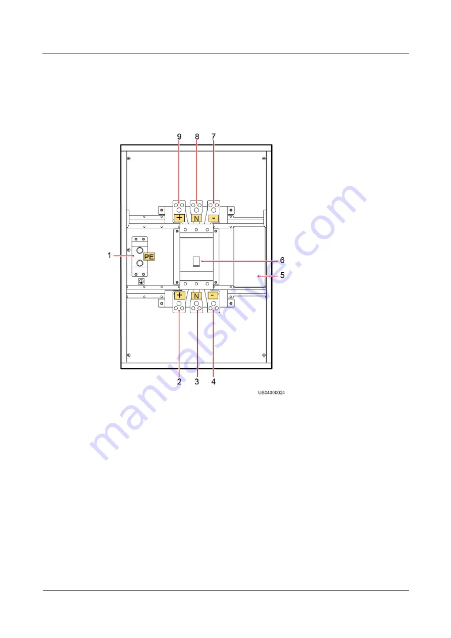
The three models of BCB boxes have the same interior. The following description uses 
PDC-0250DC0384BXA as an example. 

Figure 2-2


PDC-0250DC0384BXA interior 


(1) PE wiring 
terminals 

(2) Positive wiring 
terminals 
(connecting to the 
battery) 

(3) Neutral wiring 
terminals 
(connecting to the 
battery) 

(4) Negative wiring 
terminals 
(connecting to the 
battery) 

(5) Control board 

(6) Circuit breaker 

(7) Negative wiring 
terminals 
(connecting to the 
UPS) 

(8) Neutral wiring 
terminals 
(connecting to the 
UPS) 

(9) Positive wiring 
terminals 
(connecting to the 
UPS) 


Summary of Contents for DC0384BXA

Page 1: ...Part Number 31507247 PDC 0250 0400 0630 DC0384BXA Battery Circuit Breaker Box Quick Installation Guide Issue 03 Date 2019 05 20 HUAWEI TECHNOLOGIES CO LTD ...

Page 2: ...stomer All or part of the products services and features described in this document may not be within the purchase scope or the usage scope Unless otherwise specified in the contract all statements information and recommendations in this document are provided AS IS without warranties guarantees or representations of any kind either express or implied The information in this document is subject to ...

Page 3: ...verview 3 2 1 Exterior 3 2 2 Interior 4 2 3 BIB Board 5 3 Installation 7 3 1 Unpacking and Checking 7 3 2 Installation Preparations 7 3 2 1 Tools 7 3 2 2 Environment 8 3 2 3 Cable Connection Precautions 8 3 3 Mechanical Installation 9 3 4 Connecting Cables 13 3 4 1 Installing a Ground Cable 13 3 4 2 Installing a Power Cable 14 3 4 3 Installing a Signal Cable 18 4 Setting Parameters 28 ...

Page 4: ...t the positive neutral and negative copper bars are not short circuited Short circuits can cause a fire and result in personal injury Before operating batteries carefully read the safety precautions for battery handling and connection The BCB box may cause electric shocks and high short circuit currents Therefore before operating the BCB box get tools insulated and take off metal articles such as ...

Page 5: ...bility Therefore the environments must meet the requirements specified in this document Install the BCB box in compliance with the local laws and regulations Reserve sufficient space in front of the BCB box to facilitate maintenance Prevent liquid or other foreign matter from entering the BCB box Do not place containers with liquid near the BCB box Perform electrical connection to a specified torq...

Page 6: ...Technologies Co Ltd 3 2 Overview 2 1 Exterior The battery circuit breaker BCB box controls the connection between batteries and the uninterruptible power system UPS and protects batteries It has the following three models PDC 0250DC0384BXA PDC 0400DC0384BXA PDC 0630DC0384BXA Figure 2 1 BCB box 1 Lock 2 Handle 3 Logo 4 Cable cover ...

Page 7: ...on uses PDC 0250DC0384BXA as an example Figure 2 2 PDC 0250DC0384BXA interior 1 PE wiring terminals 2 Positive wiring terminals connecting to the battery 3 Neutral wiring terminals connecting to the battery 4 Negative wiring terminals connecting to the battery 5 Control board 6 Circuit breaker 7 Negative wiring terminals connecting to the UPS 8 Neutral wiring terminals connecting to the UPS 9 Posi...

Page 8: ... Ltd 5 2 3 BIB Board Figure 2 3 Old BIB board 1 Ports for communication and cascading with the UPS 2 Jumper cap 3 Tripping signal port 4 DIP switch 5 Jumper pin 1 6 Jumper pin 2 7 Power supply port for batteries Figure 2 4 New BIB board 1 Communications port with the UPS 2 Cascading port 3 Jumper cap 4 Reserved 5 Reserved 6 Tripping signal port ...

Page 9: ...XA Battery Circuit Breaker Box Quick Installation Guide 2 Overview Issue 03 2019 05 20 Copyright Huawei Technologies Co Ltd 6 7 DIP switch 8 Reserved 9 Reserved 10 Jumper pin 1 11 Jumper pin 2 12 Power supply port for batteries ...

Page 10: ...r immediately Check whether the fittings comply with the packing list If some fittings are missing or the models do not comply with the packing list record the information and contact your local Huawei office immediately 3 2 Installation Preparations 3 2 1 Tools Table 3 1 Tools Appearance Specifications and Name Multimeter Phillips screwdriver PH2 x 150 mm or PH3 x 250 mm Insulated adjustable wren...

Page 11: ...tective gloves Electrostatic discharge ESD gloves Insulation gloves Protective shoes Cable tie Rubber mallet Crimping tools RJ45 connector 3 2 2 Environment The BCB box is installed in environments with proper ventilation and is far away from water heat sources and flammable and explosive materials The BCB box should be far away from direct sunlight dust volatile gases corrosive materials conducti...

Page 12: ...les Install power cables for the three BCB boxes based on their input and output currents The BCB box is wall mounted or rack mounted Cables are routed in from the bottom and out from the top Reserve sufficient space on the top and bottom of the BCB box Connect cables according to terminal silk screen and wiring diagrams in this document Secure cables to the specified torques Do not short circuit ...

Page 13: ... Battery Circuit Breaker Box Quick Installation Guide 3 Installation Issue 03 2019 05 20 Copyright Huawei Technologies Co Ltd 10 Figure 3 1 Installing mounting brackets Step 2 Drill holes in the wall based on specified dimensions ...

Page 14: ...ei Technologies Co Ltd 11 Figure 3 2 Dimensions of mounting holes in the BCB box unit mm Step 3 Insert four M6 expansion bolts into the mounting holes in the wall 1 Drill holes 2 Knock expansion sleeve completely into the holes with rubber mallet 3 Partially tighten the expansion bolt 4 Remove the bolt spring washer and flat washer ...

Page 15: ... Align the four cucurbit holes in the BCB box with the bolts mentioned Then move the BCB box downwards until the screws fit into the mounting holes Step 5 Secure the four bolts the BCB box is secured to the wall Step 6 If there are multiple BCB boxes secure the other BCB boxes to the wall End Rack mounted Step 1 Install four mounting brackets on the BCB box using eight M4 screws Step 2 Install scr...

Page 16: ...4 Connecting Cables The following description uses PDC 0250DC0384BXA as an example 3 4 1 Installing a Ground Cable Step 1 Open the door of the BCB box and remove the insulation cover Step 2 Remove the top and bottom panels Step 3 Drill cable holes in the cover based on the number and cross sectional area of cables Install the grommet strip around the cable hole to prevent cables from scratches Ste...

Page 17: ...ble Secure cables to the torque specified in the guide Otherwise severe accidents such as fires may occur Single Battery String A maximum of four BCB boxes can be cascaded Two battery strings are connected to one BCB box The installation sequence and position of power cables are the same as those of a single battery string Install the power cables by referring to the method of installing a power c...

Page 18: ...Box User Manual The following describes how to connect four battery strings to four BCB boxes Step 1 Connect the power cables on the BCB box to the UPS Figure 3 6 Connecting the power cables to the UPS 1 Positive wiring terminals connecting to the positive battery input terminals on the UPS 2 Neutral wiring terminals connecting to the neutral battery input terminals on the UPS 3 Negative wiring te...

Page 19: ...he battery string 2 Neutral wiring terminals connecting to the neutral terminals on the battery string 3 Negative wiring terminals connecting to the negative terminals on the battery string Step 3 Check that the cables are connected correctly and securely End Multiple Battery Strings Step 1 Connect power cables on the BBB box to UPS battery input terminals Step 2 Connect power cables between the B...

Page 20: ...tive wiring terminal of BCB box 2 connecting to positive terminals on battery string 2 11 Neutral wiring terminal of BCB box 2 connecting to neutral terminals on battery string 2 12 Negative wiring terminal of BCB box 2 connecting to negative terminals on battery string 2 13 BCB box 3 14 BCB box 3 ground terminal 15 Positive wiring terminal of BCB box 3 connecting to positive terminals on battery ...

Page 21: ...Positive wiring terminals of the BBB box connecting to battery positive input terminals of the UPS Step 4 Check that the cables are connected correctly and securely End 3 4 3 Installing a Signal Cable When connecting cables ensure that dry contacts OL STA DRV and 0V on the UPS dry contact card correspond to control signal ports OL STA DRV and GND on the BCB box respectively If the cable length is ...

Page 22: ...ht Huawei Technologies Co Ltd 19 Figure 3 9 Connecting the control signal cable on the BCB box old BIB board Table 3 3 Mapping relationship of ports MUE05A BCB Signal Port BIB J1 Signal Port Description OL 5 OL BCB box connected STA 6 STA BCB box circuit breaker state DRV 7 DRV BCB box trip control 0V 8 GND signal grounding ...

Page 23: ...k Installation Guide 3 Installation Issue 03 2019 05 20 Copyright Huawei Technologies Co Ltd 20 Figure 3 10 Connecting the control signal cable new BIB board Figure 3 11 J1 port pin Table 3 4 Pin definitions for the J1 port No Description 1 2 3 4 5 OL 6 STA 7 DRV ...

Page 24: ...pping relationship of ports MUE05A BCB BIB J1 Description OL 5 OL BCB box connected STA 6 STA BCB box circuit breaker state DRV 7 DRV BCB box trip control 0V 8 GND signal grounding Step 2 After connecting the signal cable set toggle switch 1 to ON and toggle switch 2 to OFF for the DIP switch on the control board Figure 3 12 DIP switch old BIB board 1 Control signal port J1 2 DIP switch S1 ...

Page 25: ...pond to pins 1 and 2 of the DIP switch on the old BIB board By default toggle switch 1 is ON and toggle switch 2 is OFF The toggle switch is ON when it is switched to the silk screen ON and is OFF when switched to the other end Step 3 Check that the cables are properly connected Step 4 Reinstall the isolation board and lock the BCB box End Multiple Battery Strings Step 1 Connect a signal cable bet...

Page 26: ...BIB board Table 3 6 Mapping relationship of ports MUE05A BCB Port Connected to BIB1 J1 Port BIB1 J1 Port Connected to BIB2 J1 Port BIB2 J1 Port Connected to BIB3 J1 Port BIB3 J1 Port Connected to BIB4 J1 Port OL 5 OL 1 EXDRV 1 EXDRV 5 OL 5 OL 1 EXDRV 1 EXDRV STA 6 STA 2 EXDRV 2 EXDRV 6 STA 6 STA 2 EXDRV 2 EXDRV DRV 7 DRV 3 EXAUX 3 EXAUX 7 DRV 7 DRV 3 EXAUX 3 EXAUX 0V 8 GND 4 EXAUX 4 EXAUX 8 GND 8 ...

Page 27: ...ion Guide 3 Installation Issue 03 2019 05 20 Copyright Huawei Technologies Co Ltd 24 Figure 3 15 Connecting the signal cable of the BIB board new BIB board Figure 3 16 J1 and J2 port pin Table 3 7 Pin definitions for the J1 and J2 ports No J1 Port J2 Port 1 2 EXDRV 3 EXDRV ...

Page 28: ... to BIB1 J1 Port BIB1 J2 Port Connected to BIB2 J2 Port BIB2 J1 Port Connected to BIB3 J1 Port BIB3 J2 Port Connected to BIB4 J2 Port OL 5 OL 2 EXDRV 2 EXDRV 5 OL 5 OL 2 EXDRV 2 EXDRV STA 6 STA 3 EXDRV 3 EXDRV 6 STA 6 STA 3 EXDRV 3 EXDRV DRV 7 DRV 4 EXAUX 4 EXAUX 7 DRV 7 DRV 4 EXAUX 4 EXAUX 0V 8 GND 8 EXAUX 8 EXAUX 8 GND 8 GND 8 EXAUX 8 EXAUX Step 3 Set the status of the DIP switch on the BIB boar...

Page 29: ...DIP switch status of the BIB board old BIB board Number of BIB Boards BIB1 BIB2 BIB3 BIB4 1 Pin 1 ON Pin 2 OFF 2 Pin 1 OFF Pin 1 OFF Pin 2 OFF Pin 2 ON 3 Pin 1 OFF Pin 1 OFF Pin 1 ON Pin 2 OFF Pin 2 OFF Pin 2 OFF 4 Pin 1 OFF Pin 1 OFF Pin 1 OFF Pin 1 OFF Pin 2 OFF Pin 2 OFF Pin 2 OFF Pin 2 ON Table 3 10 DIP switch status of the BIB board new BIB board Number of BIB Boards BIB1 BIB2 BIB3 BIB4 1 S1 ...

Page 30: ...1 OFF S1 OFF S1 OFF S2 OFF S2 OFF S2 OFF S2 ON The DIP switches of the new BIB board are S1 and S2 which correspond to pins 1 and 2 of the DIP switch on the old BIB board By default toggle switch 1 is ON and toggle switch 2 is OFF The toggle switch is ON when it is switched to the silk screen ON and is OFF when switched to the other end Step 4 Check that the cables are properly connected Step 5 Re...

Page 31: ...u have not logged in enter a user name and password the preset passwords for admin and operator are both 000001 and tap on the login screen displayed Step 2 Set MUE05A connection to Enable and then set both BCB connection OL and Battery breaker STA to Enable Figure 4 1 BCB setting End UPS WebUI Step 1 Log in to the WebUI and choose Monitoring Param Settings Dry Contacts The preset passwords for ad...

Page 32: ...o Enable and then set both BCB connection OL and Battery breaker STA to Enable Figure 4 2 BCB setting End UPS New WebUI Step 1 Log in to the WebUI and choose Monitoring UPS system Running Parameter Dry contact setting The preset passwords for admin and operator on the WebUI are both Changeme Step 2 Set Mue05a connection to Enable and then set both BCB connection and Battery breaker to Enable ...

Page 33: ...PDC 0250 0400 0630 DC0384BXA Battery Circuit Breaker Box Quick Installation Guide 4 Setting Parameters Issue 03 2019 05 20 Copyright Huawei Technologies Co Ltd 30 Figure 4 3 BCB setting End ...

Reviews: