background image

5

 Replacing the Optical Module

You must disconnect the fiber optic cable from an optical module before replacing the optical
module. Disconnecting the fiber optic cable interrupts transmission of CPRI signals.

Prerequisites

l

To confirm the type of a faulty module, perform the following steps:

Run the 

DSP BTSOPTMODULE

 command on the BSC LMT.

Run the 

DSP OPTMODULE

 command on the NodeB LMT.

Run the 

DSP SFP

 command on the eNodeB LMT.

Identify the type of the faulty module according to the values of 

Rate

Wavelength

,

and 

Transmission mode

 in the output information of the command, and obtain a new

optical module of the same type as the faulty one. The type of a new optical module is
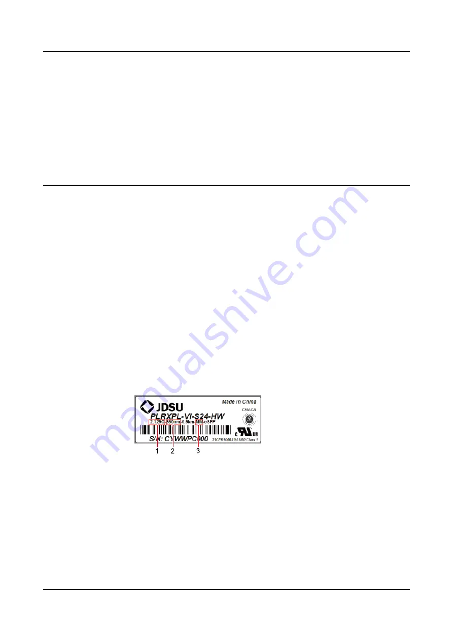
identified by the label on the new module. The following figure shows the label on an
optical module.

Figure 5-1

 Label on an optical module

(1) Maximum rate

(2) Wavelength

(3) Transmission mode


l

The type and number of optical modules to be replaced are confirmed, and new optical
modules are ready.

l

Required tools and materials are available, including an ESD box or bag, and ESD gloves.

Context

l

Optical modules are inserted into the RX TX CPRI0 and RX TX CPRI1 ports on an AAU.

AAU3940
Hardware Maintenance Guide

5 Replacing the Optical Module

Issue 01 (2015-01-15)

Huawei Proprietary and Confidential

Copyright © Huawei Technologies Co., Ltd.

16

Summary of Contents for AAU3940

Page 1: ...AAU3940 Hardware Maintenance Guide Issue 01 Date 2015 01 15 HUAWEI TECHNOLOGIES CO LTD ...

Page 2: ... be within the purchase scope or the usage scope Unless otherwise specified in the contract all statements information and recommendations in this document are provided AS IS without warranties guarantees or representations of any kind either express or implied The information in this document is subject to change without notice Every effort has been made in the preparation of this document to ens...

Page 3: ...010C00 and later Intended Audience This document is intended for l Base station installation personnel l System engineer l Site maintenance personnel Organization 1 Changes in AAU3940 Hardware Maintenance Guide This chapter describes changes in AAU3940 Hardware Maintenance Guide 2 Routine Hardware Maintenance Items Routine hardware maintenance for an AAU improves reliability of the AAU You are adv...

Page 4: ... or serious injury Indicates a potentially hazardous situation which if not avoided may result in minor or moderate injury Indicates a potentially hazardous situation which if not avoided could result in equipment damage data loss performance deterioration or unanticipated results NOTICE is used to address practices not related to personal injury Calls attention to important information best pract...

Page 5: ... x y Optional items are grouped in braces and separated by vertical bars A minimum of one item or a maximum of all items can be selected x y Optional items are grouped in brackets and separated by vertical bars Several items or no item can be selected GUI Conventions The GUI conventions that may be found in this document are defined as follows Convention Description Boldface Buttons menus paramete...

Page 6: ...ions The mouse operations that may be found in this document are defined as follows Action Description Click Select and release the primary mouse button without moving the pointer Double click Press the primary mouse button twice continuously and quickly without moving the pointer Drag Press and hold the primary mouse button and move the pointer to a certain position AAU3940 Hardware Maintenance G...

Page 7: ...aintenance Items 2 3 Powering On and Powering Off an AAU 4 3 1 Powering on an AAU 5 3 2 Powering off an AAU 6 4 Replacing an AAU 8 5 Replacing the Optical Module 16 AAU3940 Hardware Maintenance Guide Contents Issue 01 2015 01 15 Huawei Proprietary and Confidential Copyright Huawei Technologies Co Ltd vi ...

Page 8: ...to or deleted from this issue Compared with issue Draft A 2014 10 30 this issue includes the following changes Topic Change Description Entire document Some figure updates caused by the structure modification of the AAU Draft A 2013 10 30 This is a draft AAU3940 Hardware Maintenance Guide 1 Changes in AAU3940 Hardware Maintenance Guide Issue 01 2015 01 15 Huawei Proprietary and Confidential Copyri...

Page 9: ...e AAUs securely installed 2 All RF cables are free from wear cuts cracks or other damage 3 All RF cable connectors are sealed and waterproofed properly 4 All RF cable conduits are in good condition 5 All power cables are free from wear cuts cracks or other damage 6 All power cable connectors are in good condition 7 All power cable conduits are in good condition 8 All shield layers of power cables ...

Page 10: ... with perform the following corrective actions 1 Tighten all connections 2 Report any other faults found during the checking because further repairs on towers can be performed only by trained and technically qualified field engineers AAU3940 Hardware Maintenance Guide 2 Routine Hardware Maintenance Items Issue 01 2015 01 15 Huawei Proprietary and Confidential Copyright Huawei Technologies Co Ltd 3...

Page 11: ... off an AAU An AAU can be powered off in two ways normal power off and emergency power off You must power off the AAU in a normal situation such as moving the equipment or anticipating a territorial blackout You must also power off the AAU in an emergency such as a fire smoke or water damage AAU3940 Hardware Maintenance Guide 3 Powering On and Powering Off an AAU Issue 01 2015 01 15 Huawei Proprie...

Page 12: ...s Direct contact with the input voltage or indirect contact with the input voltage using a damp object may be fatal NOTICE l After unpacking the RU you must power on it within 24 hours If you power off the RU for maintenance you must restore power to the RU within 24 hours l Keep a minimum of 7 35 m 24 11 ft away from the front of the AAU after the RU is powered on and the AAU starts working Proce...

Page 13: ...ower off You must power off the AAU in a normal situation such as moving the equipment or anticipating a territorial blackout You must also power off the AAU in an emergency such as a fire smoke or water damage Procedure l Normal power off 1 Set the corresponding circuit breaker on the power equipment for the AAU to OFF l Emergency power off NOTICE Emergency power off may damage the AAU Therefore ...

Page 14: ...U 2 If time permits set the corresponding circuit breaker on the power equipment for the AAU to OFF End AAU3940 Hardware Maintenance Guide 3 Powering On and Powering Off an AAU Issue 01 2015 01 15 Huawei Proprietary and Confidential Copyright Huawei Technologies Co Ltd 7 ...

Page 15: ...SD gloves NOTICE Take proper ESD protection measures for example put on an ESD wrist strap or ESD gloves to prevent electrostatic damage to the boards modules or electronic components Step 2 Instruct the U2000 administrator to block the faulty AAU by running the BLK BRD command Step 3 Power off the AAU For detailed operations see 3 2 Powering off an AAU Step 4 Remove cables from the faulty AAU 1 O...

Page 16: ...onnects to the ground bolt on the attachment plate In this case remove the PGND cable l If the AAU is installed on a pole top the PGND cable connects to the ground bolt on the mounting support In this case do not remove the PGND cable 4 Use an M6 inner hexagon torque screwdriver to tighten the screws on the maintenance cavity and close the cover Step 5 Remove the faulty AAU AAU3940 Hardware Mainte...

Page 17: ...nstalled on a pole top use a torque screwdriver to loosen the four bolts securing the AAU and remove the AAU with both hands as shown in Figure 4 3 Figure 4 2 Removing an AAU from a Pole or Wall a Pole installation scenario b Wall mounting scenario AAU3940 Hardware Maintenance Guide 4 Replacing an AAU Issue 01 2015 01 15 Huawei Proprietary and Confidential Copyright Huawei Technologies Co Ltd 10 ...

Page 18: ... tighten the screws to 7 N m 61 95 lbf in as shown in Figure 4 4 2 Insert the attachment plate at the bottom of the AAU to the dovetail groove on the mounting bracket and use a torque screwdriver to tighten the captive screws to 7 N m 61 95 lbf in as shown in Figure 4 5 AAU3940 Hardware Maintenance Guide 4 Replacing an AAU Issue 01 2015 01 15 Huawei Proprietary and Confidential Copyright Huawei Te...

Page 19: ...lowing figure shows the installation in the wall mounting scenario installing an AAU on a pole is the same AAU3940 Hardware Maintenance Guide 4 Replacing an AAU Issue 01 2015 01 15 Huawei Proprietary and Confidential Copyright Huawei Technologies Co Ltd 12 ...

Page 20: ...ounting bracket on the pole top and use four M6 hexagon socket head cap bolts to secure the AAU to 7 N m 61 95 lbf in as shown in the following figure 2 Install the landscaping cover AAU3940 Hardware Maintenance Guide 4 Replacing an AAU Issue 01 2015 01 15 Huawei Proprietary and Confidential Copyright Huawei Technologies Co Ltd 13 ...

Page 21: ...previous record and ensure that waterproof blocks are inserted into vacant ports 3 Close the cover for the maintenance cavity of the AAU Step 8 Set the corresponding circuit breaker on the power equipment for the AAU to ON AAU3940 Hardware Maintenance Guide 4 Replacing an AAU Issue 01 2015 01 15 Huawei Proprietary and Confidential Copyright Huawei Technologies Co Ltd 14 ...

Page 22: ...0 Inform the remote engineer that the AAU has been replaced End Follow up Procedure l Place the replaced component into an ESD box or bag Then place the ESD box or bag into a foam padded carton or the packing box of the new module l Complete the fault form with detailed information about the replaced component l Contact the local Huawei office to handle the faulty component AAU3940 Hardware Mainte...

Page 23: ...tion of the command and obtain a new optical module of the same type as the faulty one The type of a new optical module is identified by the label on the new module The following figure shows the label on an optical module Figure 5 1 Label on an optical module 1 Maximum rate 2 Wavelength 3 Transmission mode l The type and number of optical modules to be replaced are confirmed and new optical modul...

Page 24: ... of the optical module and fiber optic cable Step 3 Press the latch on the optical connector and then remove the connector from the faulty optical module as shown in the following figure Figure 5 2 Removing the cables CAUTION Do not look into the optical module without eye protection after removing the fiber optic cable from the optical module Step 4 Lower the puller on the faulty optical module a...

Page 25: ...rist strap or ESD gloves and pack up all tools End Follow up Procedure l Place the replaced component into an ESD box or bag Then place the ESD box or bag into a foam padded carton or the packing box of the new module l Complete the fault form with detailed information about the replaced component l Contact the local Huawei office to handle the faulty component AAU3940 Hardware Maintenance Guide 5...

Reviews: