background image


-4-


Bellmouth (flare)…… Critical configuration of the crimp section of the contact whose function is to avoid breakage of the 

terminated conductor and assure strength of the crimp. 


Serrations ...................Deformations or cross-serrations of the material inside the wire barrel whose function is to break 

possible oxidation films on the contact and conductors during the crimping, thus assuring stable 

electrical connection. 


Contact section...........Configuration of the contact which will make electrical and mechanical connection with the 

corresponding mating contact. 


-

電線被覆

電線被覆

電線被覆

電線被覆のストリップ

のストリップ

のストリップ

のストリップ


Stripping of wire outer insulation 

-

-

ストリップ

ストリップ

ストリップ

ストリップ長

長さの

さの

さの

さの適否

適否

適否

適否


Correct stripping length 

電線のストリップ長さは、端子毎に設定されています。ストリップ長さの加工精度により圧着の作業性品質が左右

されますので注意してください。


Stripping length of the wire is specified for each contact. Correct crimping depends on accurate stripping of the wire. 

適正なストリップ長さ:圧着した際、ワイヤーバレル先

端から芯線が突き出しており、

また被覆がインシュレー

シ ョ ン バ レ ル よ り 引 っ 込 ん で い た り ワ イ ヤ ー バ レ ル 内

に入り込んでいない状態であること。


Correct  stripping  length:  After  crimping  the  conductors 

should  protrude  from  the  top  end  of  the  Wire  barrel  and  the 

Insulation  barrel  should  be  around  the  Outer  insulation,  as 

shown on the illustration on the left. Before crimping do not 

pull on the outer insulation or attempt to insert it in the Wire 

barrel.   


-

-

電線

電線

電線

電線ストリップ

ストリップ

ストリップ

ストリップ状態

状態

状態

状態


Stripped wire condition 


芯線に傷が無いこと。また一部が断線したり脱落していないこと。 


導線の長さ、被覆切断端面がバラついていたり、バラけたりしていないこと。 


Conductor should be free from any damage or partially broken or missing strands. 


The conductor and outer insulation cut-off’s must be straight. The outer insulation can not be loose. 


根元に傷をつけない 

Do not damage any individual stands


被覆切断断面/ 

Incorrect stripping


芯線の長さ/ 

Length of the 
strand


芯線突き出し/

 Conductor juts out


a :  ストリップ長さ 

a : Storipping length


No

No

No

No  


Yes

Yes

Yes

Yes  


Jul.1.2017  Copyright 2017 HIROSE ELECTRIC CO., LTD. All Rights Reserved.

Summary of Contents for ATAD-P0109

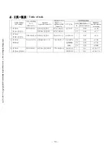
Page 1: ...扱説明書をお をお をお をお読 読 読 読みください みください みください みください また また また また いつでもすぐに いつでもすぐに いつでもすぐに いつでもすぐに読 読 読 読めるように めるように めるように めるように この この この この取扱説明書 取扱説明書 取扱説明書 取扱説明書を を を を保管 保管 保管 保管してくだ してくだ してくだ してください さい さい さい CAUTION Be sure to read this Instruction Manual carefully before using it to secure safety in operation In addition save this Instruction Manual so that it is available whenever necessary for revie...

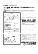
Page 2: ...に読めるように この取扱説明書を大切に保存してください 安全装置 1 本工具には 安全カバー等の安全装置は取り付いていません 圧着作業 圧着作業 圧着作業 圧着作業に に に に際 際 際 際しては しては しては しては ハンドル ハンドル ハンドル ハンドル 部 部 部 部に に に に指等挟まないよう安全に十分配慮してご使用ください 用 途 1 この工具は 本来の用途および本取扱説明書に規定された使用方法以外には使用しないでくだい 用途以外の使用に対しては 当社は責任を負いません 2 工具には 改造等を加えないでください 改造によって起きた事故に対しては 当社は責任を負 いません 保 守 1 不慣れによる事故を防ぐため 修理 調整は工具を熟知した保全技術者が本取扱説明書の指示範 囲で行ってください 不適切な修理 調整および非純正部品による事故に対しては 当社は責任 を負いません 2 ...

Page 3: ...structions specified in this Instruction Manual Hirose assumes no responsibility for any misuse of the tool other than the intended use 2 Modifications to this tool is prohibited We assume no responsibility for accidents resulting from modifications Maintenance 1 To prevent possible accidents caused by unfamiliarity with the operation of the tool repair and adjustment of the tool shall be conducte...

Page 4: ...6 圧着後 圧着後 圧着後 圧着後の の の の端子形状 端子形状 端子形状 端子形状の の の の確認 確認 確認 確認 6 6 6 6 2 6 1 良品の基準 6 2 6 2 圧着不良例 7 2 2 2 2 7 7 7 7 端子 端子 端子 端子のハウジングへの のハウジングへの のハウジングへの のハウジングへの挿入 挿入 挿入 挿入 9 9 9 9 2 7 1 ランス高さの確認 9 2 7 2 組立手順 例 10 2 7 3 ハウジング組立状態の確認 10 2 7 4 端子の引き抜き方法 10 2 7 5 組立後の確認 11 2 2 2 2 8 8 8 8 その その その その他 他 他 他 注意事項 注意事項 注意事項 注意事項 11 11 11 11 2 8 1 電線結束時の注意事項 11 2 8 2 導通耐圧チェック 11 2 8 3 端子の取り扱い 11 3 3 3 3 ...

Page 5: ...ontact after crimping 6 2 6 1 Standards for acceptable crimp 6 2 6 2 Example of defective crimping 7 2 7 Insertion of contact into housing 9 2 7 1 Checking of lance height 9 2 7 2 Assembling procedure example 10 2 7 3 Checking the assembly condition of the housing 10 2 7 4 Contact extraction 10 2 7 5 Verification of the complete contact insertion 11 2 8 Other precautions 11 2 8 1 Precautions when ...

Page 6: ...e contact and tool Do not crimp other than the specified contact or wire Do not subject the tool to physical impact or drop Do not attempt to release the moveable handle before completing full compression as this may damage the tool Handle will release after completion of the full compression The handle can not be opened before automatic release of the ratchet Do not apply excessive compression on...

Page 7: ... or foreign particles specially in the crimper and anvil areas Close the handles making sure that the crimper and anvil slide smooth without any interference Store in the dry place Routine maintenance HRS offers maintenance service to evaluate condition and performance of the tool Request this service from the place of purchase or the nearest HRS representative Repair of the tools Contact the plac...

Page 8: ...にバレル面と導線の酸化皮膜の破壊を助長し より電気的 機械的に接続の安定を狙うものです コンタクト部 コネクタの雄と雌を嵌合させた時 相手側のコンタクトと電気的に接合する部分 です Wire barrel U shaped section of the contact which is compressed around the conductors with a mechanical force Configuration and dimensions after the completion are critical for maintaining mechanical and electrical performance of the contact Insulation barrel U shaped section of the contact which is compress...

Page 9: ...ontact Correct crimping depends on accurate stripping of the wire 適正なストリップ長さ 圧着した際 ワイヤーバレル先 端から芯線が突き出しており また被覆がインシュレー ションバレルより引っ込んでいたりワイヤーバレル内 に入り込んでいない状態であること Correct stripping length After crimping the conductors should protrude from the top end of the Wire barrel and the Insulation barrel should be around the Outer insulation as shown on the illustration on the left Before crimping do not pull ...

Page 10: ...al factor in determining the correct crimp condition and must be as specified Specified wire size construction and style must be used The crimp height requirement may not be applicable with some wires although they may be within the specified dimensions Use the micrometer for measuring the crimp height to measure the crimp height 2 2 2 2 5 5 5 5 圧着部 圧着部 圧着部 圧着部の の の の引 引 引 引っ っ っ っ張 張 張 張り り り り強度...

Page 11: ...いこと 被覆はインシュレーションバレルに適正に圧着されていること 芯線がワイヤーバレルからはみ出していないこと 端子のコンタクト部に変形がないこと ランスに変形がないこと ワイヤーバレル部に大きなバリが無いこと 圧着部に亀裂やバレル外面の肌に荒れが無いこと 端子の曲りが 8 圧着条件及び圧着品質基準表 の規格を満足していること The crimp height is in the specified range The bell mouth has an is correct size The jutting amount of the conductor is correct The outer insulation is inserted in the conductor barrel The outer insulation is conect crimped in the insu...

Page 12: ...r break low pull out force or electrical connection failure 浅打ち Insufficient compression of the crimp sections 電線のストリップ寸法が不適切だったり 工具への電線のセ ットの仕方により発生する事があります 浅打ちにより芯線への負荷が直接に導線圧着部に伝わり断 線となる恐れがあります Caused by incorrect wire stripping Can cause conductor break low pull out force or electrical connection failure 芯線の突き出しが長過ぎる Too long protrusion of the conductor 電線のストリップ寸法が不適切だったり 工具への電線のセ ットの仕方により発生する...

Page 13: ... of the contact Excessive deformation of the contact will prevent insertion in the corresponding insulator housing 端子変形 ローリング Deformed contact Rolling 工具の調整状態や歯型の摩耗 工具への端子のセット状態 端子の取り扱いにより発生する事があります ローリングが 著しいと ハウジングへの挿入が行えない事があります Can be caused by the adjusted condition of the tool wear of the tool teeth positioning of the contact in the tool or handling of the contact Excessive deformation of th...

Page 14: ...左右が不均一な事によりバリ部 での端子の亀裂や 電気的接続の不安定 強度不足 端子の変形となる 恐れがあります Caused by damage or wear of the crimp sections of the tool Can cause deformation of the contact cracks or peels of the material degradation of the electrical connection or loss of the wire retention 2 2 2 2 7 7 7 7 端子 端子 端子 端子のハウジングへの のハウジングへの のハウジングへの のハウジングへの挿入 挿入 挿入 挿入 Insertion of contact into housing 2 2 2 2 7 7 7 7 1 1 1 1 ランス ランス ランス ラ...

Page 15: ...4 4 4 4 端子 端子 端子 端子の の の の引 引 引 引き き き き抜 抜 抜 抜き き き き方法 方法 方法 方法 Contact extraction 端子のハウジングからの引き抜き方法は コネクタにより異なります 端子の抜き治具が専用で用意されてい るものもあります 詳細は コネクタのカタログなどで確認を行ってください Contact extraction procedure varies with a specific connector insulator housing Specific extraction tools are listed in applicable catalogs ランスがハウジングの角窓に引っ掛かっているもの 端子が矢印方向に若干ガタがあり 浮遊性がある The lance is properly engaged in the recta...

Page 16: ...res do not interfere with the mating with the corresponding part Do not insert any test probes or other pins into the socket contact as it may damage it causing electric discontinuities 2 2 2 2 8 8 8 8 3 3 3 3 端子 端子 端子 端子の の の の取 取 取 取り り り り扱 扱 扱 扱い い い い Handling of the terminated wires 端子には必要以上に触れないでください 端子に触れる際は 腐蝕防止の為なるべく手袋などを着用してください 端子の上に物を置いたり 端子を落下しますと変形しますので乱暴な取り扱いはしないでください 端子が絡んだ時は 無理に引...

Page 17: ...製造番号表示 Serial number クリンパ Crimper アンビル Anvil HRS マーク表示 HRS logo 製品名表示 Tool number 原産国表示 Country of origin 製造年月日 Date of manufacture ラチェット Ratchet 可動ハンドル Moving handle 抜き差しピン Release pin 端子ホルダー Contact holder if applicable 237 231 5 55 5 110 Jul 1 2017 Copyright 2017 HIROSE ELECTRIC CO LTD All Rights Reserved ...

Page 18: ...2022SC 676 1032 0 20 0 53 φ1 8 1 HT304 DF33 2022S 550 0300 1 DF33A 2022SC 676 1093 5 UL1007 22 0 34 φ1 7 2 HT304 GT8E 2022S 780 0042 6 GT8E 2022SC 758 0101 2 AVSS0 3 0 37 φ1 5 20 0 52 φ1 34 23 0 30 φ1 02 3 HT304 HR34B 1 150 0107 9 HR34B SC1 111 134 0051 7 UL20276 日立電線製 撚線 25 0 20 φ0 88 CAVS0 5 0 5 φ1 6 1 7 4 HT304 GT25H 2024S 780 0044 1 GT25H 2024SCF 775 0039 6 CAVS0 3 0 3 φ1 4 1 5 Jul 1 2017 Copy...

Page 19: ...against the stop Caution Some tools may have contact stops held in place with the back spring Insert the contact against it but do not deflect the spring 4 端子のバレルの位置を目印にして 目視で電線 の位置合わせを行なってください ケーブルの 端末処理寸法は 8 圧着条件及び圧着基準表 をご参照ください 5 ハンドルがラチェットを解除するまで握ってハ ンドルを開いてください 6 圧着された端子を 電線を持って引き出してく ださい 7 正規に圧着されたかを確認してください 8 圧着条件及び圧着基準表 をご参照ください 注意 注意 注意 注意 端子 端子 端子 端子を を を を工具 工具 工具 工具に に に に挿入 挿入 挿入 挿入した...

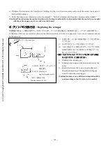
Page 20: ...ge used Anvil side is stationary and can not be removed 1 圧着工具ヘッド部にある抜き差しピンを引き抜い てください 2 矢印方向にクリンパを引き抜いてください 3 180 回転させ ご使用になるケーブルサイズの刻 印表示が見えるように取り付け 抜き差しピンを 差し込んでください 注意 注意 注意 注意 UL UL UL ULスタイルによってクリンパを スタイルによってクリンパを スタイルによってクリンパを スタイルによってクリンパを使 使 使 使い い い い分 分 分 分ける ける ける ける場合 場合 場合 場合 もございます もございます もございます もございます ご ご ご ご注意 注意 注意 注意ください ください ください ください 1 Withdraw the releasing pin 2 Withdraw the...

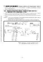
Page 21: ...onditions and crimping quality standard with respect to the crimp height and the tensile strength 2 Check to be sure that the contact that has been crimped using the tool is within the standard of good product with respect to the shape Caution 1 To use a wire a covering diameter of which is different from that of the standard wire please contact our Business Division or the distributor in your are...

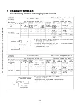
Page 22: ... 2 9 DF33 2022SC and DF33A 2022SC have the 3rd barrel See the illustration given below Check also the width dimension of the 3rd barrel Width dimension 2 5 2 9 工具製品番号 Tool product No HT304 GT8E 2022S 電線ストリップ寸法 Stripping dimension of wire 2 0 2 5 標準適合電線 Standard applicable wire 圧着品質基準 Crimping quality standard クリンプハイト 項目 Item 寸法 Dimension 項目 Item 寸法 Dimension 適合端子製品番号 Applicable contact product No ...

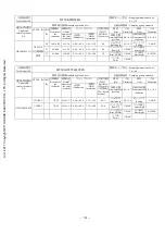
Page 23: ...AX バリ高さ Burr hight 0 1MAX HR34B SC1 111 UL20276 日立電線製 撚線 ツイスト Twist 3 MAX 工具製品番号 Tool product No HT304 GT25H 2024S 電線ストリップ寸法 Stripping dimension of wire 3 6 4 0 標準適合電線 Standard applicable wire 圧着品質基準 Crimping quality standard クリンプハイト 項目 Item 寸法 Dimension 項目 Item 寸法 Dimension 適合端子製品番号 Applicable contact product No STYLE AWG 芯線構成 Structure of the conductor 被覆外径 Outside diameter of the outer insulati...

Page 24: ...om the improper use of the tools including failure to follow the instructions given in this Instruction Manual This includes repair or modification conducted by any third party other than Hirose Electric Co Ltd 5 The specifications of the product are subject to change without notice CAUTION 1 本書の内容の一部または全部を無断転載することは固くお断りします 2 本書の内容については 将来予告無しに変更する事があります 3 当社では 本製品の運用を理由とする損失 逸失利益等の請求につきましては責任を負 い...

Page 25: ...ls Court Simi Valley Calif 93065 6235 Phone Tele Fax 805 5227958 805 5223217 Hirose Electric GmbH Zeppelinstraze 42 73760 Ostfildern Kemnat Phone Tele Fax 0711 4560021 0711 4560729 Hirose Electric UK Ltd Crownhill Business Centre 22 Vincent Avenue Crownhill Milton Keynes MK80AB Phone Tele Fax 0908 260616 0908 563309 HIROSE KOREA Co Ltd 472 5 Mok Nae Dong Ansen City Seoul Phone Tele Fax 02 864 5075...

Reviews: