


Shenzhen Hpmont Technology Co., Ltd.
Appendix A MODBUS Communication Protocol
HD3Z Series User Manual V1.2
-69-
Appendix A
MODBUS Communication Protocol
1.
Introduction
By using the host computer (including communication devices such as computer and PLC), user can
operate to read-write the controller’s function code, read the status parameters and write the control
command etc. The inverter is in slave mode when it is communicating.
Optical Fiber Communication Interface
HD3Z has in-built optical transceiver single fiber mode. User optical flange interface is ST type:
Port
Asyn, half-duplex
Format
1-8-2 (1 start bit, 8 data bits, 2 stop bits), no parity, RTU
Baut rate
9600bps
Relative setting
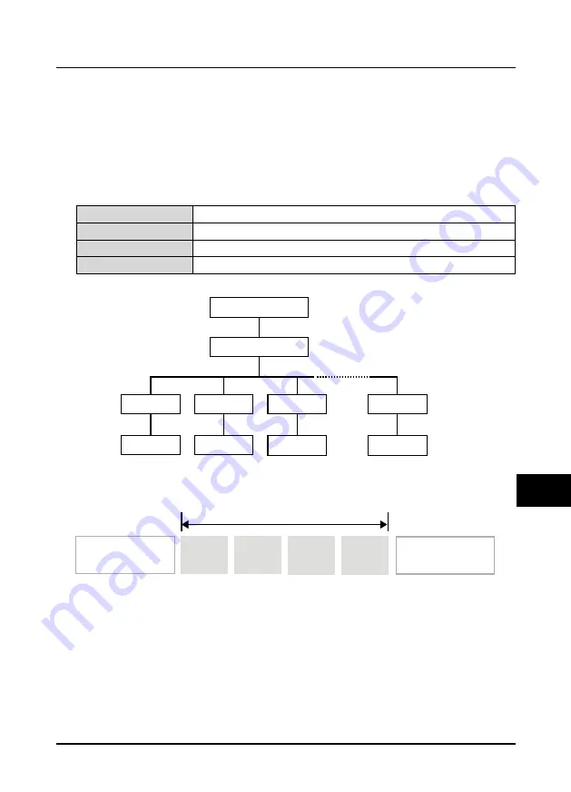
Network Mode
Protocol Format
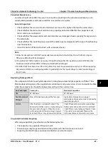
MODBUS supports RTU mode, with corresponding frame format as shown below:
MODBUS adopts “Big Endian” encoding mode, higher byte prior to lower byte at sending.
•
The idle time of frame head and frame tail passing bus should be not less than 3.5 bytes.
•
Slave address = 0, it means broadcast address.
•
Data checking relies on CRC-16. The whole information need be checked. The concrete CRC
checking is referred to the page 76.
PC
RS485 switching module
HD3Z
HD3Z
External device
External device
External device
HD3Z
HD3Z
Optical fiber
Optical fiber
Optical fiber
Optical fiber
RS485
bus
External device
Modbus data frame
RTU model
Slave
address
Frame head (at least
3.5 character spacing)
Frame head (at least
3.5 character spacing)
Function
code
Data
Checking
A