background image


31 

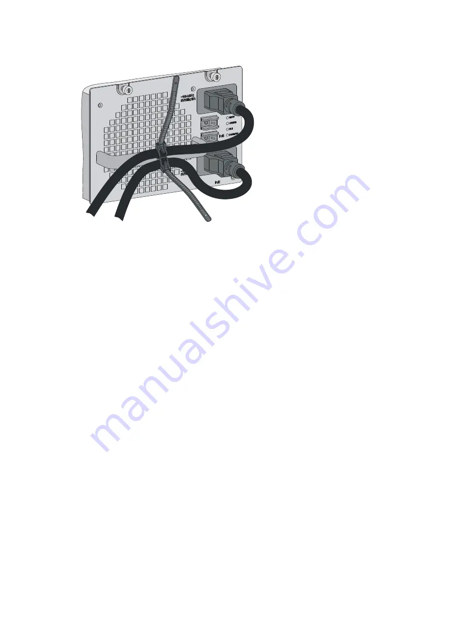
Figure 26 Connecting the PSR2800-ACV power cord 


Connecting the PSR6000-ACV 

The PSR6000-ACV is a built-in power supply with AC input and DC output. It can provide the switch 
with both system power and PoE power, which can be controlled through separate power switches. 
Before connecting the PSR6000-ACV power cord, make sure the system and PoE power switches 
are off. 

The PSR6000-ACV provides four power sockets: 


One system power socket, as shown by callout 5 in 

Figure 27


Three PoE power sockets, as shown by callout 8 in 

Figure 27

Connecting the system power cord is the same as connecting the PoE power cord. The following 
illustrates how to connect the system power cord. 

Summary of Contents for FlexNetwork 7500 Switch

Page 1: ...HPE FlexNetwork 7500 Switch Series Installation Guide Part number 5998 7465s Document version 6W102 20160520 ...

Page 2: ...nd 12 212 Commercial Computer Software Computer Software Documentation and Technical Data for Commercial Items are licensed to the U S Government under vendor s standard commercial license Links to third party websites take you outside the Hewlett Packard Enterprise website Hewlett Packard Enterprise has no control over and is not responsible for information outside the Hewlett Packard Enterprise ...

Page 3: ...n air filter optional 17 Mounting the switch in the rack 19 Connecting the grounding cable 20 Connecting the grounding cable to a grounding strip 20 Grounding the switch through the AC power supply 21 Grounding the switch through the RTN wire of a DC power supply 22 Installing FRUs 23 Attaching an ESD wrist strap 23 Installing MPUs service modules 24 Installing a power supply 25 Installing a power...

Page 4: ...SFP QSFP module 60 Replacing a CFP module 60 Replacing an SFP QSFP QSFP to SFP DAC cable 61 Replacing the PoE DIMM 61 Document conventions and icons 63 Conventions 63 Network topology icons 64 Support and other resources 65 Accessing Hewlett Packard Enterprise Support 65 Accessing updates 65 Websites 66 Customer self repair 66 Remote support 66 Documentation feedback 66 Appendix A Chassis views an...

Page 5: ...R1400 A 106 PSR1400 D 107 PSR2800 ACV 108 PSR6000 ACV 109 Appendix D Transceiver modules 112 40 GE CFP transceiver modules 112 40 GE QSFP transceiver modules 113 40 GE QSFP DAC cables 113 10 GE XFP transceiver modules 114 10 GE SFP transceiver modules 115 10 GE SFP DAC cables 116 1000 100 Mbps SFP transceiver modules 117 Appendix E Cables 119 Ethernet twisted pair cable 119 RJ 45 connector 119 Cab...

Page 6: ...ic label 130 Affixing a label to a device 131 Guidelines 131 Examples 131 Engineering labels for network cables 131 Engineering labels for optical fibers 132 Engineering labels for DC power cords 134 Engineering labels for AC power cords 135 Engineering labels for devices 136 Appendix G Cable management 138 Cable management guidelines 138 Cable management examples 140 Index 142 ...

Page 7: ...ld get caught in the chassis when you install and maintain the switch Electricity safety Clear the work area of possible hazards such as ungrounded power extension cables missing safety grounds and moist floors Locate the emergency power off switch in the room before installation Shut the power off at once in case accident occurs Remove all the external cables including power cords before moving t...

Page 8: ... from the fiber port might hurt your eyes The HPE 7500 switches are class 1 laser products Examining the installation site The HPE 7500 switches can only be used indoors To ensure correct operation and long service life of your switch the installation site must meet the requirements in this section Weight support Evaluate the floor loading as compared to the actual weight of the switch and its acc...

Page 9: ...5 RH Cleanliness Mechanically active substances buildup on the chassis might result in electrostatic adsorption which causes poor contact of metal components and contact points In the worst case electrostatic adsorption can cause communication failure Table 3 Mechanically active substance concentration limit in the equipment room Substance Particle diameter Concentration limit Dust particles 5 µm ...

Page 10: ...teps to satisfy the power supply requirements of the 7500 switches 1 Calculate the total power consumption The total power consumption of a 7500 switch depends on module type and quantity and fan tray power consumption If the switch provides PoE power the total power consumption also depends on PoE power consumption For more information about the total power consumption of the 7500 switches see Ap...

Page 11: ...5 Figure 1 Airflow for the 7506 V chassis 1 Power supply air inlet vents 2 Power supply air outlet vents 3 Chassis air inlet vents 4 Chassis air outlet vents ...

Page 12: ...er devices The equipment room is a minimum of 3 m 9 84 ft high The dimensions of the rack are sufficient for the chassis For more information about chassis specifications see Appendix A Chassis views and technical specifications Installation accessories and tools Installation accessories Table 5 Installation accessories Product code Item Quantity Compatible switch model module 5185 8627 Console ca...

Page 13: ...ts 7510 12 sets All 7500 switch models 5185 8765 ESD wrist strap 1 All 7500 switch models 5187 9151 Removable cable tie As required All 7500 switch models NOTE Figures for the mounting bracket cable management bracket and power cord management bracket in Table 5 are for illustration only Tools and equipment Prepare the following tools and equipment yourself Mechanical lift Phillips screwdrivers P1...

Page 14: ...8 NOTE The rack installation accessories and tools vary by rack model and are not included in this section For more information see the installation guide for the rack ...

Page 15: ...g slide rails and cage nuts to the rack For how to install slide rails see Installing slide rails For how to install cage nuts see Installing cage nuts for attaching mounting brackets Installing accessories to the chassis Accessories to be installed on the chassis For how to mount brackets and cable management brackets see Installing mounting brackets and cable management brackets For how to insta...

Page 16: ... Before installing the slide rails verify that the slide rails can support the weight of the switch For the weights of the 7500 switches see Appendix A Chassis views and technical specifications As a best practice order the HPE X421 A Series Chassis Universal 4 Post Rack Mounting Kit JC665A For more information about the kit see Appendix B FRUs and compatibility matrixes Make sure the rack meets t...

Page 17: ...een holes on a rack post as shown in Figure 5 Each rack post requires six screws to secure the slide rail You only need to mark the uppermost square hole and lowermost square hole for installation Mark the square holes at the same height on the other three rack posts NOTE One rack unit has three holes the middle of which is an auxiliary installation hole and the other two are standard installation...

Page 18: ...ea between holes 3 Install six cage nuts on the square holes in each rack post as shown in Figure 6 Figure 6 Installing a cage nut 4 Align the installation holes on the front end of a slide rail with the cage nuts on the front rack post and secure them with screws as shown in Figure 7 1 RU 1 RU 1 RU 1 1 1 1 1 ...

Page 19: ...rear end of the slide rail touch the cage nuts on the rear rack post Then fasten the screws TIP Install a screw in each mounting hole of the slide rail to ensure its weight bearing capacity 6 Repeat step 4 and step 5 to install the other slide rail Make sure the two slide rails are at the same height so the device can be placed on them horizontally ...

Page 20: ...Installed slide rails Installing cage nuts for attaching mounting brackets 1 Determine and mark the cage nut installation holes on the front rack posts as shown in Figure 9 2 Install cage nuts as shown in Figure 6 ...

Page 21: ...brackets Before installing the switch in the rack install the mounting brackets and cable management brackets shipped with the switch Mounting brackets are used for attaching the chassis to the rack and cable management brackets are used for cabling the switch 7506 V Install the mounting brackets and cable management brackets separately to the chassis For more information see Installing the cable ...

Page 22: ...r part of the switch They are installed in the same way To install a cable management bracket 1 Unpack the cable management brackets 2 Attach the cable management bracket to the chassis and align the screws with the screw holes in the chassis as shown in Figure 10 3 Fasten the screws Figure 10 Installing cable management brackets on a 7506 V Installing the cable management brackets on other models...

Page 23: ...es of the switch Other models Facing the front of the switch mount the mounting bracket with a cable management bracket to the left of the switch and mount the mounting bracket without a cable management bracket to the right of the switch where the fan tray is located Figure 12 Installing the mounting brackets 7503 Installing an air filter optional Air filters are optional for the 7500 switches As...

Page 24: ... or rear panel and then insert the captive screws into the screw holes on the chassis 3 Faster the captive screws as shown by callout 2 in Figure 13 Figure 13 Installing an air filter on a 7506 V 1 Front air filter 2 Rear air filter Installing an air filter on other chassis models 1 Unpack the air filter and fastening strips 2 Align the screw holes in the fastening strip with the screw holes in th...

Page 25: ...ing the switch on the slide rails do not leave go of your hands immediately because this might tip and damage the switch and even cause bodily injury To mount the switch in the rack 1 Face the rear of the chassis towards the front of the rack 2 Use a minimum of two people to lift the switch until the bottom of the switch is a little higher than the slide rails on the rack 3 Place the switch on the...

Page 26: ...ing cable to the earthing system in the equipment room Do not connect it to a fire main or lightning rod When a grounding strip is available at the installation site connect the grounding cable through the grounding strip To connect the grounding cable 1 Unpack the grounding cable Use the provided grounding cable yellow green grounding cable The provided grounding cable is compliant with the NEBS ...

Page 27: ... power cord is reliably grounded at the power distribution room or AC power supply transformer side Make sure the AC receptacle on the switch is correctly connected to the AC power supply If the switch is AC powered and no grounding strip is available at the installation site you can ground the switch through the AC power supply as shown in Figure 17 Figure 17 Grounding the switch through the AC p...

Page 28: ...ent room is reliably grounded If the switch is powered by a 48 VDC power supply and no grounding strip is available at the installation site you can ground the switch through the return RTN wire of the DC power supply as shown in Figure 18 Figure 18 Grounding the switch through the RTN wire of the DC power supply ...

Page 29: ...onents wear an ESD wrist strap and ensure that it is reliably grounded when installing modules To use an ESD wrist strap 1 Make sure the switch is reliably grounded For how to ground your switch see Installing the switch 2 Wear the wrist strap 3 Tighten the wrist strap to keep good skin contact Make sure the resistance reading between your body and the ground is between 1 and 10 megohms 4 Insert t...

Page 30: ...modules are the same Unless otherwise stated MPUs and service modules are collectively referred to as modules in this document These modules are hot swappable To install a module 1 Wear an ESD wrist strap and make sure it has good skin contact and is reliably grounded For more information see Attaching an ESD wrist strap 2 Remove the blank filler if any from the slot to be used Keep the blank fill...

Page 31: ...he requirements of the switch To ensure good ventilation install a blank filler panel over an empty slot The switch uses 1 1 power redundancy and supports AC and DC power input For more information about power supplies see Appendix B FRUs and compatibility matrixes For the a switch that uses the PSR1400 A or PSR2800 ACV when the switch consumes less than 650 W power and does not use PoE use the fo...

Page 32: ... to be used Keep the blank filler secure for future use 3 Unpack the power supply and verify that the power supply model is correct 4 Insert the power supply with its upside up 5 Grasping the handle of the module with one hand and supporting the module bottom with the other gently push the power supply along the guide rails into the slot until it has firm contact with the slot 6 Use a Phillips scr...

Page 33: ...10 A busbars are available in the equipment room but the PSR1400 A PSR2800 ACV and PSR6000 ACV power supplies require a 16 A power cord AC You need to use a 16 A busbar and make sure that the AC power supply system can provide enough power For the power cords used in different countries or regions see Appendix B FRUs and compatibility matrixes Connecting the PSR320 A PSR650 A 1 Install a bail latc...

Page 34: ...power cord to the handle of the power supply as shown in Figure 23 4 Connect the other end of the power cord to the AC power socket Figure 23 Connecting the power cord Connecting the PSR1400 A 1 Unpack the power cord and verify the power cord model the PSR1400 A uses a 16 A AC power cord 2 Connect the power cord to the power socket on the power supply and ensure a good contact 3 Secure the power c...

Page 35: ...input and DC output It can provide the switch with both system power and PoE power which can be controlled through separate power switches Before connecting the PSR2800 ACV power cord make sure the system and PoE power switches are off The PSR2800 ACV provides two power sockets One system power socket as shown by callout 2 in Figure 25 One PoE power socket as shown by callout 6 in Figure 25 ...

Page 36: ...r to connecting the system power cord This section takes the system power cord for example To connect the system power cord 1 Unpack the power cord and verify the power cord model the PSR2800 ACV uses a 16 A AC power cord 2 Connect the power cord to the power socket on the power supply and ensure a good contact 3 Secure the power cord to the handle of the power supply as shown in Figure 26 4 Conne...

Page 37: ...ed through separate power switches Before connecting the PSR6000 ACV power cord make sure the system and PoE power switches are off The PSR6000 ACV provides four power sockets One system power socket as shown by callout 5 in Figure 27 Three PoE power sockets as shown by callout 8 in Figure 27 Connecting the system power cord is the same as connecting the PoE power cord The following illustrates ho...

Page 38: ... PoE power cord is similar to connecting the system power cord This section takes the system power cord for example To connect the system power cord 1 Unpack the power cord and verify the power cord model the PSR6000 ACV uses a 16 A AC power cord 2 Connect the power cord to the power socket on the power supply and ensure a good contact 3 Secure the power cord to the handle of the power supply as s...

Page 39: ...for the PSR320 D and PSR650 D are similar This section uses the PSR650 D as an example To connect the PSR650 D 1 Remove the protection cover from the power supply 2 Loosen the captive screw on the wiring terminal with a Phillips screwdriver 3 Connect the wire marked with the negative polarity symbol or L to the negative terminal on the power supply 4 Connect the wire marked with the positive polar...

Page 40: ...ide on each wiring terminal 2 Loosen the captive nuts on four wiring terminals with an M6 socket wrench and remove the captive nut spring washer and one flat washer in turn from each wiring terminal 3 Connect the wire marked with the negative polarity symbol or L to the negative terminal block on the power supply 4 Connect the wire marked with the positive polarity symbol or M N to the positive te...

Page 41: ...es APs and web cameras The following PoE types are available Type 1 Power delivered by a single port 0 to 15 4 W voltage range 44 V to 57 V maximum current 350 mA This PoE type provides power to classes 0 to 3 PDs Type 2 Power delivered by a single port 0 to 30 W voltage range 50 V to 57 V maximum current 600 mA This PoE type provides power to classes 0 to 4 PDs To set up a PoE system the followin...

Page 42: ...MMH Type 1 LSQ1GV48SC0 48 LSBM1POEDIMMH Type 1 LSQ1GV40PSC0 40 LSBM1POEDIMMH Type 1 NOTE The model of a module is LSQM prefixed on the module package and LSQ prefixed on the module panel For example LSQ1GV48SD0 and LSQM1GV48SD0 identify the same module Make sure the total PoE power required by all PDs connected to a PSE is not greater than the maximum PSE power For more information about the maxim...

Page 43: ...t can be either 110 VAC or 220 VAC Installing a PoE DIMM CAUTION Avoid touching the components on the PoE DIMM and PCB during installation and removal of a PoE DIMM If no PoE DIMM is in place or the module is not fully seated the interface module cannot supply power though other functions work well The PoE DIMM slot is a reverse insertion prevention slot to help you identify the direction for inst...

Page 44: ... 1 Wear an ESD wrist strap and make sure it has a good skin contact and is reliably grounded For more information see Attaching an ESD wrist strap 2 Make sure the module is sturdy Then find the PoE DIMM slot there is a Master mark on the PCB under the slot on the PCB 3 Pull the white clips on the two sides of the PoE DIMM slot outward as shown by callout 1 in Figure 31 4 Unpack the master PoE DIMM...

Page 45: ... Packard Enterprise Figure 33 Setting up a PoE system by using the A RPS800 1 NEG terminal 2 RTN terminal 3 Grounding point 4 DC input 5 A RPS800 6 AC input To connect the A RPS800 to the switch 1 Remove the blank panel covering the PoE port of the switch 2 Remove the nuts and flat washers from the terminals 3 Connect the ring terminal with a sign on the power cord to the NEG terminal on the PoE p...

Page 46: ... Connecting the power cords to the switch 6 Connect the H2 7 connector of the PoE power cord to the DC output port of the A RPS800 and then fasten the screw Figure 35 Connecting the power cords to the A RPS800 1 2 ...

Page 47: ...module optional CAUTION To avoid component damage read this section carefully before installing a transceiver module Do not remove the dust plug from a transceiver module until you are ready to connect an optical fiber to the module Before you install a transceiver module remove the optical fiber if any from it The transceiver modules available for the switch include SFP SFP XFP and QSFP Installin...

Page 48: ... the module For the installation procedure see Connecting your switch to the network Figure 37 Installing an XFP SFP SFP QSFP module Installing a CFP module 1 Wear an ESD wrist strap and make sure it makes good skin contact and is reliably grounded For more information see Attaching an ESD wrist strap 2 Unpack the CFP module Do not touch the golden plating of the module 3 Holding both sides of the...

Page 49: ...FP QSFP or QSFP to SFP DAC cable 1 Wear an ESD wrist strap and make sure it makes good skin contact and is reliably grounded For more information see Attaching an ESD wrist strap 2 Unpack the cable 3 Connect the cable connector to the port Make sure the cable connector is the right side up The bend radius of the cable must be a minimum of eight times the cable diameter Figure 39 Connecting an SFP ...

Page 50: ...connector for connecting to the console port of the switch and a DB 9 connector for connecting to the 9 core serial port on the terminal Figure 40 shows the console cable and Table 11 shows its pinouts Figure 40 Console cable connecting the serial port and the console port Table 11 Pinouts for the console cable connecting the serial port and the console port RJ 45 pin Signal DB 9 pin Signal 1 RTS ...

Page 51: ...o not support hot swapping To connect a PC to an operating device first connect the PC end To disconnect a PC from an operating device first disconnect the device end To connect the console cable to the console port 1 Connect the DB 9 connector of the console cable to the serial port on a PC or terminal 2 Connect the RJ 45 connector of the console cable to the console port on the MPU of the switch...

Page 52: ...econd 9 600 Data bits 8 Stop bits 1 Parity None Flow control None Powering on the switch Before powering on the switch verify that the following conditions are met The switch has been steadily mounted All the modules have been correctly installed All the communication cables fibers power cords and grounding cables have been correctly connected The voltage of power supply can meet the requirements ...

Page 53: ...y Speed 667MHz BootWare Size 1536KB Flash Size 4MB BASIC CPLD Version 001 EXTENDED CPLD Version 008A PCB Version Ver B BootWare Validating Press Ctrl B to access EXTENDED BOOTWARE MENU Loading the main image files Loading file flash 7500 cmw710 system R7168 bin Done Loading file flash 7500 cmw710 devkit R7168 bin Done Loading file flash 7500 cmw710 manufacture R7168 bin Done Loading file flash 750...

Page 54: ... your switch to the network To connect your switch to the network through twisted pair cables 1 Connect one end of the twisted pair cable to the RJ 45 Ethernet port of your switch 2 Connect the other end of the twisted pair cable to the RJ 45 Ethernet port of the access device in the network 3 Examine the port LEDs for incorrect connection For more information about the LED status see Appendix C L...

Page 55: ...For the allowed maximum tensile load and crush load see Appendix E Cables The installation of different optical fiber connectors is similar To connect your switch to the network through optical fibers 1 Install a transceiver module into the port 2 Remove the dust cover of the optical fiber connector and clean the end of the optical fiber 3 Remove the dust plug of the transceiver module connect one...

Page 56: ...MPO optical fiber connector to connect a QSFP module Connecting the switch to the network through copper cables For how to connect the 7500 switch to the network through copper cables see Installing FRUs MPO plug QSFP module ...

Page 57: ...en the switch is operating Figures for the chassis and FRUs are for illustration only Replacing mounting brackets 1 Remove the screws that secure the chassis to the rack 2 Cooperate with one or more people to lift the chassis by holding chassis handles or by supporting the chassis bottom Pull out the chassis along the guide rails until the space is enough for replacing the mounting brackets Figure...

Page 58: ...r and the power supplies to be replaced are of different models power off the switch before replacement to avoid damage to the switch When you use two power supplies to supply power to the switch make sure each power supply has a separate circuit breaker Before replacing a power supply turn off the circuit breaker on the power supply If you use a PSR650 A PSR650 D power supply together with a PWR ...

Page 59: ...res see Installing FRUs After removing the power supply if you do not install a new power supply install a blank panel As shown by callout 3 in Figure 49 align the screws on the blank panel with the screw holes on the switch and then use a screwdriver to fasten the screws on the blank panel Figure 49 Removing the power supply Replacing a module The module replacement procedures for the 7500 switch...

Page 60: ...e heat dissipation of the switch and prevent dust from entering the switch Figure 50 Replacing a module Replacing a fan tray CAUTION When replacing the fan tray do not touch the rotating fans to avoid bodily injury To ensure correct operation of the switch install a new fan tray within five minutes after the fan tray is removed Make sure the fan tray handle is pushed into the slot after installati...

Page 61: ...y by its bottom with one hand hold the fan tray handle with the other hand to pull the fan tray out of the slot 6 Put the removed fan tray on the antistatic mat or its original shipping materials Figure 51 Removing a fan tray from a 7506 V Installing a fan tray 1 Wear an ESD wrist strap and make sure it has a good skin contact and is reliably grounded For more information see Installing FRUs 2 Unp...

Page 62: ...n by callout 2 in Figure 53 hold the handle of the fan tray to pull the fan tray out of the slot 5 Put the removed fan tray on an antistatic mat or its original shipping materials Figure 53 Removing a fan tray from other models Installing a fan tray 1 Wear an ESD wrist strap and make sure it has a good skin contact and is reliably grounded For more information see Installing FRUs 2 Unpack a new fa...

Page 63: ...s two air filters on its front and rear panels For how to replace the air filters see Replacing air filters on a 7506 V Other models of the 7500 switches have only one air filter For how to replace it see Replacing an air filter for the other models Replacing air filters on a 7506 V 1 Use a Phillips screwdriver to remove the captive screws on the front and rear air filters as shown by callout 1 in...

Page 64: ... filter as shown by callout 1 in Figure 56 2 Seize the captive screws on the air filter and slowly pull the air filter out of the chassis as shown by callout 2 in Figure 56 3 Install the cleaned air filter to the switch For the installation procedures see Installing the switch Figure 56 Removing an air filter for the other models ...

Page 65: ...card To replace a CF card 1 Log in to the switch to execute the umount command For how to log in to the switch see Connecting your switch to the network 2 Use a hard object to press the eject button of the CF card reader as shown by callout 1 in Figure 57 The reader ejects the card part way out of the slot 3 Remove the CF card from the reader and put it in an antistatic shielding bag 4 Install a n...

Page 66: ...dust plug on the removed module and put the remove module into its original shipping materials 6 Install a new module For the installation procedures see Installing FRUs 7 Connect fibers to the new module Figure 58 Removing an SFP transceiver module Replacing a CFP module 1 Wear an ESD wrist strap and make sure it makes good skin contact and is reliably grounded For more information see Installing...

Page 67: ...QSFP to SFP DAC cable 1 Wear an ESD wrist strap and make sure it has a good skin contact and is reliably grounded For more information see Installing FRUs 2 Gently press the cable connector in and then pull the pull latch on the cable outward to pull out the cable connector 3 Install a new cable For the installation procedures see Installing FRUs Figure 60 Removing an SFP DAC cable Replacing the P...

Page 68: ...own by callout 1 in Figure 61 4 Pull the PoE DIMM out along the guide rails as shown by callout 2 in Figure 61 5 Put the removed PoE DIMM on its original shipping materials 6 Install a new PoE DIMM For the installation procedures see Installing FRUs Figure 61 Removing a PoE DIMM ...

Page 69: ...st one x y Asterisk marked square brackets enclose optional syntax choices separated by vertical bars from which you select one choice multiple choices or none 1 n The argument or keyword and argument combination before the ampersand sign can be entered 1 to n times A line that starts with a pound sign is comments GUI conventions Convention Description Boldface Window names button names field name...

Page 70: ... Represents an access controller a unified wired WLAN module or the access controller engine on a unified wired WLAN switch Represents an access point Represents a wireless terminator unit Represents a wireless terminator Represents a mesh access point Represents omnidirectional signals Represents directional signals Represents a security product such as a firewall UTM multiservice security gatewa...

Page 71: ...s provide a mechanism for accessing software updates through the product interface Review your product documentation to identify the recommended software update method To download product updates go to either of the following Hewlett Packard Enterprise Support Center Get connected with updates page www hpe com support e updates Software Depot website www hpe com support softwaredepot To view and u...

Page 72: ...lf repair Hewlett Packard Enterprise customer self repair CSR programs allow you to repair your product If a CSR part needs to be replaced it will be shipped directly to you so that you can install it at your convenience Some parts do not qualify for CSR Your Hewlett Packard Enterprise authorized service provider will determine whether a repair can be accomplished by CSR For more information about...

Page 73: ...r feedback include the document title part number edition and publication date located on the front cover of the document For online help content include the product name product version help edition and publication date located on the legal notices page ...

Page 74: ...IMPORTANT For regulatory identification purposes every 7500 serial switch is assigned a regulatory model number RMN These regulatory numbers should not be confused with the marketing name HPE 7500 or product codes Table 14 MPU models Product code Description Alias JD196A HPE FlexNetwork 7502 Main Processing Unit LSQ1MPUA0 JC697A HPE FlexNetwork 7502 TAA compliant Main Processing Unit JD220A HPE Fl...

Page 75: ...E0 JH217A HPE FlexNetwork 7500 2 4Tbps Fabric w 8 port GbE 10GbE and 2 port 40GbE TAA compliant Main Processing Unit Table 15 Service module models Product code Description Alias JD197B HPE FlexNetwork 7500 48 port 100Base FX SA Module LSQ1FP48SA0 JD198B HPE FlexNetwork 7500 48 port 10 100Base TX PoE upgradable SA Module LSQ1FV48SA0 JD199B HPE FlexNetwork 7500 48 port Gig T PoE upgradable SA Modul...

Page 76: ...GbE Combo PoE upgradable SC Module LSQ1GV24PSC0 JC792A HPE FlexNetwork 7500 4 port 40GbE QSFP SC Module LSQ1QGS4SC0 JG373A HPE FlexNetwork 7500 4 port 40GbE CFP SC Module LSQ1QGC4SC0 JD191A HPE FlexNetwork 7500 8 port 10 GbE XFP SD Module LSQ1TGX8SD0 JC713A HPE FlexNetwork 7500 8 port 10 GbE XFP SD TAA compliant Module JD229B HPE FlexNetwork 7500 48 port Gig T PoE SD Module LSQ1GV48SD0 JC712A HPE ...

Page 77: ...HPE FlexNetwork 7500 48 port 1000BASE T SE TAA compliant Module JH213A HPE FlexNetwork 7500 48 port 1000BASE T w PoE SE Module LSQM1GV48SE0 JH221A HPE FlexNetwork 7500 48 port 1000BASE T with PoE SE TAA compliant Module JH210A HPE FlexNetwork 7500 44 port GbE 4 port 10GbE SE Module LSQM1GP44TSSE0 JH218A HPE FlexNetwork 7500 44 port GbE 4 port 10GbE SE TAA compliant Module JH211A HPE FlexNetwork 75...

Page 78: ... AC Power Supply PSR2800 ACV JD227A HPE FlexNetwork 7500 6000W AC Power Supply PSR6000 ACV Table 17 Mounting accessories Product code Description Alias JC665A HPE FlexNetworkHP X421 A Series Chassis Universal 4 Post Rack Mounting Kit Rack Mounting Kit Table 18 PoE DIMM models Product code Description Alias JD192B HPE FlexNetwork 7500 48 port PoE DIMM 48 port PoE DIMM JC671A HPE FlexNetwork 7500 24...

Page 79: ...Network X600 1G Compact Flash Card CF 1G Chassis views The figures in this chapter are for illustration only 7502 Figure 62 7502 front and rear panels 1 Power supply section 2 MPU section 3 Service module section 4 Fan tray section 5 PoE PEM slot 7503 S Figure 63 7503 S front and rear panels 1 Power supply section 2 MPU section 3 Service module section 4 Fan tray section 5 PoE power input port ...

Page 80: ...74 7503 Figure 64 7503 front panel 1 MPU section 2 Service module section 3 Power supply section 4 Fan tray section 1 2 3 3 4 ...

Page 81: ...75 7506 Figure 65 7506 front panel 1 MPU section 2 Service module section 3 Power supply section 4 Fan tray section ...

Page 82: ...76 7506 V Figure 66 7506 V front panel 1 MPU section 2 Power supply section 3 Service module section 4 Fan tray section 1 2 3 2 4 ...

Page 83: ...t panel 1 Service module section 2 MPU section 3 Power supply section 4 Fan tray section Technical specifications The following modules are not supported in Release R7xxx LSQ1MPUA0 LSQ1CGP24TSC0 LSQ1CGV24PSC0 LSQ1SRPB0 LSQ1SRPD0 ...

Page 84: ...hts and dimensions Table 21 Chassis weights and dimensions Model Weight Height Width Depth 7502 15 kg 33 07 lb 175 mm 6 89 in 4 RU 436 mm 17 17 in 420 mm 16 54 in 7503 S 15 kg 33 07 lb 175 mm 6 89 in 4 RU 436 mm 17 17 in 420 mm 16 54 in 7503 30 kg 66 14 lb 441 mm 17 36 in 10 RU 436 mm 17 17 in 420 mm 16 54 in 7506 40 kg 88 18 lb 575 mm 22 64 in 13 RU 436 mm 17 17 in 420 mm 16 54 in 7506 V 50 kg 11...

Page 85: ...6 in LSQ1FV48SA0 2 89 kg 6 37 lb 40 mm 1 57 in 399 mm 15 71 in 352 mm 13 86 in LSQ1GP24TSA0 2 77 kg 6 11 lb 40 mm 1 57 in 399 mm 15 71 in 352 mm 13 86 in LSQ1GV24PSA0 2 80 kg 6 17 lb 40 mm 1 57 in 399 mm 15 71 in 352 mm 13 86 in LSQ1GV48SA0 3 09 kg 6 81 lb 40 mm 1 57 in 399 mm 15 71 in 352 mm 13 86 in LSQ1GP12SC0 2 66 kg 5 86 lb 40 mm 1 57 in 399 mm 15 71 in 352 mm 13 86 in LSQ1GP24SC0 2 78 kg 6 1...

Page 86: ...08 kg 6 79 lb 40 mm 1 57 in 399 mm 15 71 in 352 mm 13 86 in LSQ1GP24TEB0 3 04 kg 6 70 lb 40 mm 1 57 in 399 mm 15 71 in 352 mm 13 86 in LSQ1GP24TSD0 3 01 kg 6 64 lb 40 mm 1 57 in 399 mm 15 71 in 352 mm 13 86 in LSU3WCMD0 3 62 kg 7 98 lb 40 mm 1 57 in 399 mm 15 71 in 352 mm 13 86 in LSU1FWCEA0 3 90 kg 8 60 lb 40 mm 1 57 in 399 mm 15 71 in 352 mm 13 86 in LSU3FWCEA0 3 90 kg 8 60 lb 40 mm 1 57 in 399 ...

Page 87: ...3 mm 7 99 in 365 mm 14 37 in 7506 fan tray 2 2 kg 4 85 lb 28 mm 1 10 in 331 mm 13 03 in 365 mm 14 37 in 7506 V fan tray 3 2 kg 7 05 lb 45 mm 1 77 in 375 mm 14 76 in 369 mm 14 53 in 7510 fan tray 3 0 kg 6 61 lb 28 mm 1 10 in 497 mm 19 57 in 380 mm 14 96 in Module power consumption Module power consumption The power consumption of the modules depends on the module model and state Table 25 shows the ...

Page 88: ...W 85 W LSQ1GP24TSC0 25 W 45 W LSQ1GT24SC0 42 W 50 W LSQ1GV48SC0 60 W 90 W LSQ1TGX2SC0 30 W 40 W LSQ1GV24PSC0 30 W 60 W LSQ1P24XGSC0 40 W 55 W LSQ1T24XGSC0 50 W 75 W LSQ1GV40PSC0 41 W 95 W LSQ1QGC4SC0 52 W 85 W LSQ1QGS4SC0 70 W 90 W LSQM1TGS12EC0 91 W 146 W LSQM2TGS16SF0 52 W 75 W LSQ1TGS8SC0 75 W 95 W LSQ1TGX8SD0 73 W 120 W LSQ1TGX4SD0 53 W 80 W LSQ1TGX4EB0 53 W 80 W LSQ1TGX2SD0 43 W 55 W LSQ1TGX2...

Page 89: ...Minimum fan tray power consumption Maximum fan tray power consumption 7502 7 5 W 14 5 W 7503 S 14 5 W 14 5 W 7503 15 5 W 27 5 W 7506 24 5 W 42 5 W 7506 V 30 W 45 5 W 7510 28 W 48 5 W Total power consumption For the 7502 7503 S 7503 7506 7506 V or 7510 the total power consumption of the switch equals its system power consumption plus its PoE power consumption System power consumption The system pow...

Page 90: ...ation Model Max system power consumption full and max configuration Max module and fan tray power consumption full and max configuration 7502 AC 330 W 300 W 7502 DC 330 W 300 W 7503 S AC 380 W 350 W 7503 S DC 380 W 350 W 7503 AC 600 W 550 W 7503 DC 600 W 550 W 7506 AC 1100 W 950 W 7506 DC 1100 W 950 W 7506 V AC 1100 W 950 W 7506 V DC 1100 W 950 W 7510 AC 1600 W 1450 W 7510 DC 1600 W 1450 W PoE pow...

Page 91: ...3 7506 7510 1440 W 7506 V 800 W 7502 2 7503 3 7506 6 7506 V 6 7510 10 LSQ1CGV24PS C0 24 0 to 15 4 W 370 W 7502 2 7503 3 7506 6 7506 V 6 7510 10 LSQ1GV24PSC 0 24 0 to 15 4 W 370 W 7502 2 7503 3 7506 6 7506 V 6 7510 10 LSQ1GV24PSA 0 24 0 to 15 4 W 370 W 7502 2 7503 3 7506 6 7506 V 6 7510 10 LSQ1FV48SA0 48 0 to 15 4 W 740 W 7502 2 7503 3 7506 6 7506 V 6 7510 10 LSQ1GV48SA0 48 0 to 15 4 W 740 W 7502 2...

Page 92: ...on hour of the switch is 0 9 total power consumption of the modules plus power consumption of the fan tray 0 9 3 4121 Table 29 shows the heat dissipation for each switch model Table 29 Heat dissipation Model Heat dissipation BTU h 7502 1024 7503 S 1190 7503 1870 7506 3200 7506 V 3200 7510 4900 For the power consumption of the modules and fan trays of the 7500 switches see Module power consumption ...

Page 93: ...w speed Sound pressure level when the fan tray operates at middle speed Sound pressure level when the fan tray operates at full speed 7503 51 6 dBA 54 6 dBA 56 1 dBA 7506 53 6 dBA 56 2 dBA 57 7 dBA 7506 V 52 1 dBA 55 1 dBA 56 2 dBA 7510 53 5 dBA 55 8 dBA 56 7 dBA ...

Page 94: ...s Table 31 MPU specifications 1 Model Port quantity Console port Network management port CF card slot Other ports LSQ1MPUA0 1 1 1 N A LSQ1CGV24PSC0 1 1 N A 20 x 10 100 1000Base T RJ 45 ports 4 x combo interfaces LSQ1CGP24TSC0 1 1 N A 16 x FE GE SFP ports LC 8 x combo interfaces LSQ1SRPB0 Salience VI 1 1 1 N A LSQ1SRPD0 Salience VI Plus 1 1 1 N A LSQ1SRP1CB0 Salience VI Turbo 1 1 1 N A LSQ1SRP2XB0 ...

Page 95: ...Not supported Not supported LSQ1CGV2 4PSC0 Not supported Supported Not supported Not supported Not supported Not supported LSQ1SRPB 0 Salience VI Not supported Not supported Supported Supported Supported Supported LSQ1SRPD 0 Salience VI Plus Not supported Not supported Supported Supported Supported Supported LSQ1SRP1 CB0 Salience VI Turbo Not supported Not supported Supported Supported Supported S...

Page 96: ...ort Category 5 twisted pair cable LSQ1GP12SC0 12 1000BASE X SFP LC fiber port FE GE SFP module LSQ1GP24SC0 24 1000BASE X SFP LC fiber port FE GE SFP module LSQ1GP48SC0 48 1000BASE X SFP LC fiber port FE GE SFP module LSQ1GP24TSC0 24 16 1000BASE X SFP LC fiber ports 8 combo interfaces Category 5 twisted pair cable FE GE SFP module LSQ1GT24SC0 24 10 100 1000BASE T RJ45 copper port Category 5 twisted...

Page 97: ...ule 10 GE SFP DAC cable LSQ1TGX8SD0 8 10GBASE R XFP LC fiber port 10 GE XFP module LSQ1TGX4SD0 4 10GBASE R XFP LC fiber port 10 GE XFP module LSQ1TGX4EB0 4 10GBASE R XFP LC fiber port 10 GE XFP module LSQ1TGX2SD0 2 10GBASE R XFP LC fiber port 10 GE XFP module LSQ1TGX2EB0 2 10GBASE R XFP LC fiber port 10 GE XFP module LSQ1GP48SD0 48 1000BASE X SFP LC fiber port FE GE SFP module LSQ1GP48EB0 48 1000B...

Page 98: ...he modules see the module manuals A combo interface is a logical interface that contains an SFP port and an RJ 45 Ethernet port Only one of them can be activated at a time The module models listed in Table 34 are marked on the module panels They might be slightly different from the module models marked on the module packages For example LSQ1QGS4SC0 and LSQM1QGS4SC0 identify the same module LSQ1QGS...

Page 99: ...opper ports 2 GE combo interfaces Category 5 twisted pair cable GE SFP module Power system Restrictions and guidelines Before you order a power supply make sure you have read the following restrictions and guidelines A chassis must be configured with a minimum of one power supply To improve power supply availability you can configure a chassis with two power supplies for redundancy The power suppl...

Page 100: ...W 220 VAC No N A PSR1400 D 48 VDC to 60 VDC 1400 W Yes 6720 W PSR2800 AC V 100 VAC to 240 VAC 50 60Hz 1150 W 110 VAC Yes 1150 W 1400 W 220 VAC Yes 1400 W PSR6000 AC V 100 VAC to 240 VAC 50 60Hz 1150 W 110 VAC Yes One PoE input 1200 W Two PoE inputs 2400 W Three PoE inputs 3600 W 1400 W 220 VAC Yes One PoE input 1800 W Two PoE inputs 3600 W Three PoE inputs 5300 W NOTE The maximum PoE output power ...

Page 101: ...ly cannot be installed on the chassis Fan trays The fans trays are shipped with the 7500 switches and have been installed in the 7500 switches If the fan tray of a switch fails order a compatible fan tray to replace the faulty one Table 38 shows the available fan trays for different models of 7500 switches Table 38 Fan tray specifications Fan tray Number of fans Fan diameter Maximum rotating speed...

Page 102: ...EDs in this section is 0 5 Hz Table 39 LEDs at a glance LEDs MPU LEDs Management Ethernet port LEDs Power supply status LEDs Fan tray status LEDs Module status LEDs MPU active standby status LED CF card status LED RJ 45 Ethernet port LEDs Combo interface LEDs SFP port LEDs SFP port LEDs QSFP port LEDs XFP port LEDs Service module LEDs RJ 45 Ethernet port LEDs Combo interface LEDs SFP port LEDs SFP...

Page 103: ... status LED 6 Power supply status LED Management Ethernet port LEDs Management Ethernet copper port LED The LSQM3MPUA0 MPU uses a LINK ACT LED to indicate the link status and data forwarding status of the management Ethernet port Table 40 Management Ethernet copper port LED description for the LSQM3MPUA0 MPU LINK ACT LED status Description Flashing green A link is present and the port is receiving...

Page 104: ...tus of the power supplies see Table 43 for the LED description If the MPU provides multiple LEDs with numbers for example PWR1 and PWR2 each LED corresponds to a pluggable power supply with the same number the power supply number is marked on the chassis See Table 44 for the LED description If the MPU provides only one power status LED PWR see Table 45 for the LED description Table 43 Power supply...

Page 105: ...ble Off No power supply is installed No power supply is outputting power because one of the following conditions exists The power supplies are faulty or switched off The power cords are disconnected The external power supply is unavailable Fan tray status LEDs Fan tray status LED varies by MPU model If the MPU provides one set of LEDs OK and FAIL to indicate the status of the fan tray see Table 46...

Page 106: ...QM2MPUD0 LSQM1SRP8X2QE0 Table 50 Module status LED description RUN ALM LED status Description Flashing green The module is operating correctly Fast flashing green 4 Hz The module is loading software If the LED flashes continuously the software versions of the switch and the module do not match Steady red The module is starting up or faulty Flashing red The temperature of the module exceeds the upp...

Page 107: ...ription ACTIVE LED status Description On The MPU is active Off The MPU is in standby status The MPU is faulty You can locate the problem by examining MPU LED status CF card status LED Each MPU provides a CF card status LED CFS to indicate the status of the CF card Table 53 CF card status LED description LED LED status Description CFS On The CF card is in position Off The CF card is not in position...

Page 108: ...ate the port The other port of the combo port is then automatically shut down and becomes inactive SFP port LEDs The MPU provides an SFP port LED for each SFP port to indicate the link status and data receiving forwarding status of the SFP ports Table 56 SFP port LED description LED LED status Description SFP port status LED Flashing The SFP port is receiving or sending data Steady on A link is pr...

Page 109: ...or sending data On Off A link is present but no data is being received or sent Off Off No link is present Service module LEDs RJ 45 Ethernet port LEDs The service modules provide RJ 45 Ethernet port LEDs to indicate the link status and data receiving forwarding status of the corresponding Ethernet ports Table 60 RJ 45 Ethernet port LED description LED status Description Flashing The port is receiv...

Page 110: ...g status of the corresponding SFP port Table 62 SFP port LED description LED status Description Flashing The port is receiving or sending data On A link is present Off No link is present SFP port LEDs The service modules provide SFP port LEDs to indicate the link status and data receiving forwarding status of the corresponding SFP port Table 63 SFP port LED description for the LSQ1TGS8SC0 service ...

Page 111: ...P port Table 66 QSFP port LED description Status Description Flashing The port is receiving or sending data On A link is present Off No link is present CFP port LEDs The service modules provide CFP port LEDs to indicate the link status and data receiving forwarding status of the CFP ports Table 67 CFP port LED description LED status Description Flashing The port is receiving or sending data On A l...

Page 112: ...een The power supply is operating correctly Red The power supply is operating incorrectly because one of the following conditions exists The power supply generates an alarm and enters the protection state because of input under voltage output short circuit output over current output over voltage or over temperature A fan failure has occurred Off A power input problem has occurred because one of th...

Page 113: ...cted The external power supply is unavailable PSR1400 D The PSR1400 D power supply provides four red green status LEDs Table 71 PSR1400 D power supply LED description LED Status Description INPUT Green The power is input correctly and the system power output switch is turned on Red A power input problem has occurred because the input voltage is out of the rated voltage range Off No power is input ...

Page 114: ...wer supply provides five red green status LEDs Table 72 PSR2800 ACV power supply LED description LED Status Description INPUT Green The power is input correctly Red A power input problem has occurred because the input voltage is out of the rated voltage range Off No power is input because one of the following conditions exists The power supply is faulty The system input power cord is disconnected ...

Page 115: ...s output correctly Red A PoE power output problem has occurred because one of the following conditions exists The PoE output voltage is out of the rated voltage range The PoE power switch is turned off Off No PoE power is output because one of the following conditions exists The power supply is faulty The PoE input power cord is disconnected The external power supply is unavailable PSR6000 ACV The...

Page 116: ...oE power PoE 1 is input correctly Red A power input problem has occurred to PoE 1 because the input voltage of PoE 1 is out of the rated voltage range Off No power of PoE 1 is input because one of the following conditions exists The power supply is faulty The input power cord of PoE 1 is disconnected The external power supply is unavailable PoE IN2 Green The PoE power PoE 2 is input correctly Red ...

Page 117: ...wing conditions exists The power supply is faulty The input power cords of PoE 1 PoE 2 and PoE 3 are disconnected The external power supply is unavailable PoE FAN Green The PoE fans are operating correctly Red The PoE fans are operating incorrectly because one of the following conditions exists A PoE fan failure has occurred The PoE power switch is turned off Off No PoE power is input because one ...

Page 118: ... transceiver modules compatible with the modules see the module manuals The 7500 Switch Series supports the following transceiver modules and cables 40 GE CFP transceiver modules 40 GE QSFP transceiver modules 40 GE QSFP DAC cables 10 GE XFP transceiver modules 10 GE SFP transceiver modules 10 GE SFP DAC cables 1000 100 Mbps SFP transceiver modules 40 GE CFP transceiver modules Table 74 40 GE CFP ...

Page 119: ...ceiver 850 nm MPO 50 125 µm multi mode optical fiber 300 m 984 25 ft JG709A HPE X140 40G QSFP MPO MM 850nm CSR4 300m Transceiver 850 nm MPO 50 125 µm multi mode optical fiber 400 m 492 13 ft JG661A HPE X140 40G QSFP LC LR4 SM 10km 1310nm Transceiver 1271 nm 1291 nm 1311 nm 1331 nm LC 9 125 µm single mode optical fiber 10 km 6 21 miles NOTE The JG661A transceiver module cannot be connected to a 10 ...

Page 120: ... Cable 3 m 9 84 ft JG331A HPE X240 40G QSFP to 4x10G SFP 5m Direct Attach Copper Splitter Cable 5 m 16 40 ft Product code Description Cable length Remarks JG329A HPE X240 40G QSFP to 4x10G SFP 1m Direct Attach Copper Splitter Cable 1 m 3 28 ft Used for connecting 40 GE QSFP ports and 10 GE SFP ports JG330A HPE X240 40G QSFP to 4x10G SFP 3m Direct Attach Copper Splitter Cable 3 m 9 84 ft JG331A HPE...

Page 121: ...1542 94 9 125 N A 80 km 49 71 miles JG231A HPE X180 10G XFP LC LH 80km 1558 98nm DWDM Transceiver 1558 98 9 125 N A 80 km 49 71 miles JG232A HPE X180 10G XFP LC LH 80km 1559 79nm DWDM Transceiver 1559 79 9 125 N A 80 km 49 71 miles JG233A HPE X180 10G XFP LC LH 80km 1560 61nm DWDM Transceiver 1560 61 9 125 N A 80 km 49 71 miles NOTE The 9 125µm single mode fibers used by modules JG226A through JG2...

Page 122: ...mode optical fiber 80 km 49 71 miles JL250A HPE X130 10G SFP LC LH80 tunable XCVR 1550 nm LC 9 125 µm single mode optical fiber 80 km 49 71 miles 10 GE SFP DAC cables The 10 GE SFP DAC cables are used to connect SFP interfaces Table 80 10 GE SFP DAC cable specifications Product code Description Connector Length JD095C HPE X240 10G SFP SFP 0 65m DA Cable SFP 0 65 m 2 13 ft JD096B HPE X240 10G SFP S...

Page 123: ...C 9 125 µm single mode optical fiber 40 km 24 86 miles JD063B HPE X125 1G SFP LC LH70 Transceiver 1550 nm LC 9 125 µm single mode optical fiber 70 km 43 50 miles JD103A HPE X120 1G SFP LC LH100 Transceiver 1550 nm LC 9 125 µm single mode optical fiber 100 km 62 14 miles JD098B HPE X120 1G SFP LC BX 10 U Transceiver RX 1490 nm TX 1310 nm LC 9 125 µm single mode optical fiber 10 km 6 21 miles JD099B...

Page 124: ...cal fiber 15 km 9 32 miles JD090A HPE X110 100M SFP LC LH40 Transceiver 1310 nm LC 9 125 µm single mode optical fiber 40 km 24 86 miles JD091A HPE X110 100M SFP LC LH80 Transceiver 1550 nm LC 9 125 µm single mode optical fiber 80 km 49 71 miles JD100A HPE X115 100M SFP LC BX 10 U Transceiver TX 1310 nm RX 1550 nm LC 9 125 µm single mode optical fiber 15 km 9 32 miles JD101A HPE X115 100M SFP LC BX...

Page 125: ...ransmit data QSFP to SFP DAC cable QSFP port at one end and SFP port at the other end Connects a QSFP port to an SFP port Ethernet twisted pair cable An Ethernet twisted pair cable consists of four pairs of insulated wires twisted together It mainly transmits analog signals and is advantageous in transmitting data over shorter distances The maximum transmission distance is 100 m 328 08 ft RJ 45 co...

Page 126: ...aximum speed of 100 Mbps with a bandwidth of 100 MHz Category 5e Transmits data at a maximum speed of 1000 Mbps with a bandwidth of 100 MHz Category 6 Transmits data at a maximum speed of 10 Gbps with a bandwidth of 250 MHz NOTE The RJ 45 Ethernet ports use category 5 or higher Ethernet twisted pair cables for connection Based on pinouts Ethernet twisted pair cables can be classified into straight...

Page 127: ...i directional data cable A 2 Tx Send data BIDA Bi directional data cable A 3 Rx Receive data BIDB Bi directional data cable B 4 Reserved BIDC Bi directional data cable C 5 Reserved BIDC Bi directional data cable C 6 Rx Receive data BIDB Bi directional data cable B 7 Reserved BIDD Bi directional data cable D 8 Reserved BIDD Bi directional data cable D Table 85 RJ 45 MDI X port pinouts Pin 10BASE T ...

Page 128: ...opriate length of the cable sheath The length is typically that of the RJ 45 connector 3 Untwist the pairs so that they can lie flat and arrange the colored wires based on the wiring specifications 4 Cut the top of the wires even with one another Insert the wires into the RJ 45 end and make sure the wires extend to the front of the RJ 45 end and make good contact with the metal contacts in the RJ ...

Page 129: ... is yellow It permits transmission over longer distances Multi mode patch cord The jacket is orange It permits transmission over shorter distances Patch cords are classified into SC LC and FC patch cords based on interface type The length of a patch cord can be 0 5 m 1 64 ft 1 m 3 28 ft 2 m 6 56 ft 3 m 9 84 ft 5 m 16 40 ft and 10 m 32 81 ft Pigtail cord A pigtail cord is an optical fiber that has ...

Page 130: ...and use 10 GE SFP Cu standard cables Figure 76 SFP DAC cable 1 Connector 2 Pull latch QSFP DAC cable You can use QSFP DAC cables to connect the QSFP ports Figure 77 QSFP DAC cable 1 Connector 2 Pull latch QSFP to SFP DAC cable A QSFP to SFP DAC cable provides one QSFP connector at one end and four SFP connectors at the other end 1 2 ...

Page 131: ...125 Figure 78 QSFP to SFP DAC cable 1 QSFP connector 2 QSFP pull latch 3 SFP connector 4 SFP pull latch 1 2 3 4 ...

Page 132: ... the cable A mark TO is located at the lower right corner of the label to identify the peer end of the cable on which the label is affixed As shown in Figure 79 write a signal cable label as follows Write the position of the cable in Area 1 Write the position of the cable on the peer end in Area 2 Area 3 is the part that is folded up inside the label when the label is affixed to the cable Figure 7...

Page 133: ...is bar shaped with fixed dimensions It is applicable to both signal cables and power cords A mark TO is located at the upper left corner in the right area of the label to identify the peer end of the cable on which the label is affixed The meaning of the dividing lines is the same as labels for signal cables ...

Page 134: ...mation about using a label printer see the user guide of the printer To write labels use black markers A marker has two nibs Be sure to use the smaller nib to write labels Affixing labels After printing or writing a label remove the label from the bottom page and affix it to the signal cable or the identification plate of the power cord Affixing a label to a signal cable Typically a label is affix...

Page 135: ...angular area on the identification plate You can stick the label to either side of the identification plate Be sure to affix the labels on the same side of the identification plates A cable tie is bundled 2 cm 0 79 in away from the connector You can affix the label to other positions as needed Figure 82 shows how to affix a label when a cable is laid horizontally TO B02 03 Stick side 12 1 2 3 4 5 ...

Page 136: ...abling or on the right side of the cable in vertical cabling Make sure the label is facing out as shown in Figure 85 Figure 85 Affixed labels Affixing a generic label The requirements for affixing a generic label are the same as affixing a label on a signal cable For more information see Affixing a label to a signal cable For the example of affixed labels see Figure 83 ...

Page 137: ...f power cords with identification plates on the same side The positions of up down right or left are all based on the viewpoint of the engineering person who is working on the label Examples The label examples in this document are for reference only Engineering labels for network cables These labels are affixed to Ethernet cables that connect modules in a chassis Table 87 Information on a label af...

Page 138: ...rt number on the switch For the server end Rack number and chassis number or the specific location of the server if the server is laid separately On a label for the Ethernet cable that connects the switch and a terminal For the switch end Rack number chassis number and Ethernet port number or the specific location of the switch if the switch is laid separately The definitions of the rack number an...

Page 139: ...MN can be the name of the equipment room B Chassis number C Slot number D Fiber port number R Optical receiving interface T Optical transmitting interface N A Figure 88 Example of a label on an optical fiber between two devices A01 01 05 05 R The local end of the optical fiber is connected to Optical Receiving Interface 05 on Slot 5 Chassis 01 in the rack on Row A Column 01 in the equipment room G...

Page 140: ...e range of 01 to 99 for example 01 01 C Column number of the terminal device R Optical receiving interface T Optical transmitting interface N A Figure 89 Example of a label on an optical fiber between the device and the ODF ODF G01 01 01 R The local end of the optical fiber is connected to the optical receiving terminal on Row 01 Column 01 of the ODF in Row G Column 01 in the equipment room A01 01...

Page 141: ...re 90 Example of labels on a DC power cord A01 B08 48V2 loaded cabinet side The power cord is 48V2 DC supply which is from the 8th connecter on the second row of 48V bus bar in the cabinet on Row A and Column 1 in the equipment room B03 48V2 distribution box side The power cord is 48V2 DC supply which is from the loaded cabinet on Row B Column 03 in the equipment room In the power distribution box...

Page 142: ...s The label only carries location information about the peer equipment and the power socket while information of the local end is not necessary Make sure labels are affixed in the correct direction That is after the cable ties are bundled onto the cable the identification plates with the labels should face up and the text on the labels in the same cabinet must be in the same direction as shown in ...

Page 143: ...137 Figure 92 Example of a device label ...

Page 144: ...ther If you route them in parallel make sure the space between a power cord bundle and a signal cable bundle is at least 30 mm 1 18 in Use the correct ties to bind the cables Do not bind cables with joined ties The distances between cable ties must be three to four times the cable diameter Bind and route the cables neatly inside the rack and make sure the cables are not kinked or bent Do not tie c...

Page 145: ...xcess from the ties leaving no sharp or angular tips as shown in Figure 95 Figure 95 Cutting the cable ties Route bind and attach excess cables for easy safe maintenance activities and proper operations Do not tie the power cords to the slide rails When you connect a cable to an articulated part for example when you connect a grounding cable to a rack door leave enough slack in cables Make sure th...

Page 146: ...ing figures are for illustration only Figure 96 Network cable management Figure 97 Optical fiber management Use strapping tapes to carefully bind optical fibers Avoid excessive force For more information see the instructions shipped with the strapping tapes ...

Page 147: ...141 Figure 98 Power cord management ...

Page 148: ...eering labels for devices 136 Engineering labels for network cables 131 Engineering labels for optical fibers 132 ESD prevention 2 Ethernet interface modules 90 F Fan tray status LEDs 99 Fiber connector 123 G General safety recommendations 1 Generic labels 127 Grounding 4 Grounding the switch through the AC power supply 21 Grounding the switch through the RTN wire of a DC power supply 22 H Handlin...

Page 149: ...eplacing air filters on a 7506 V 57 Replacing an air filter for the other models 58 Replacing an SFP QSFP QSFP to SFP DAC cable 61 Replacing an XFP SFP SFP QSFP module 60 Requirements 35 Restrictions and guidelines 93 RJ 45 connector 119 RJ 45 Ethernet port LEDs 103 RJ 45 Ethernet port LEDs 101 S Setting terminal parameters 46 Setting up the configuration environment 44 SFP port LEDs 102 SFP port ...

Reviews: