background image

System board components

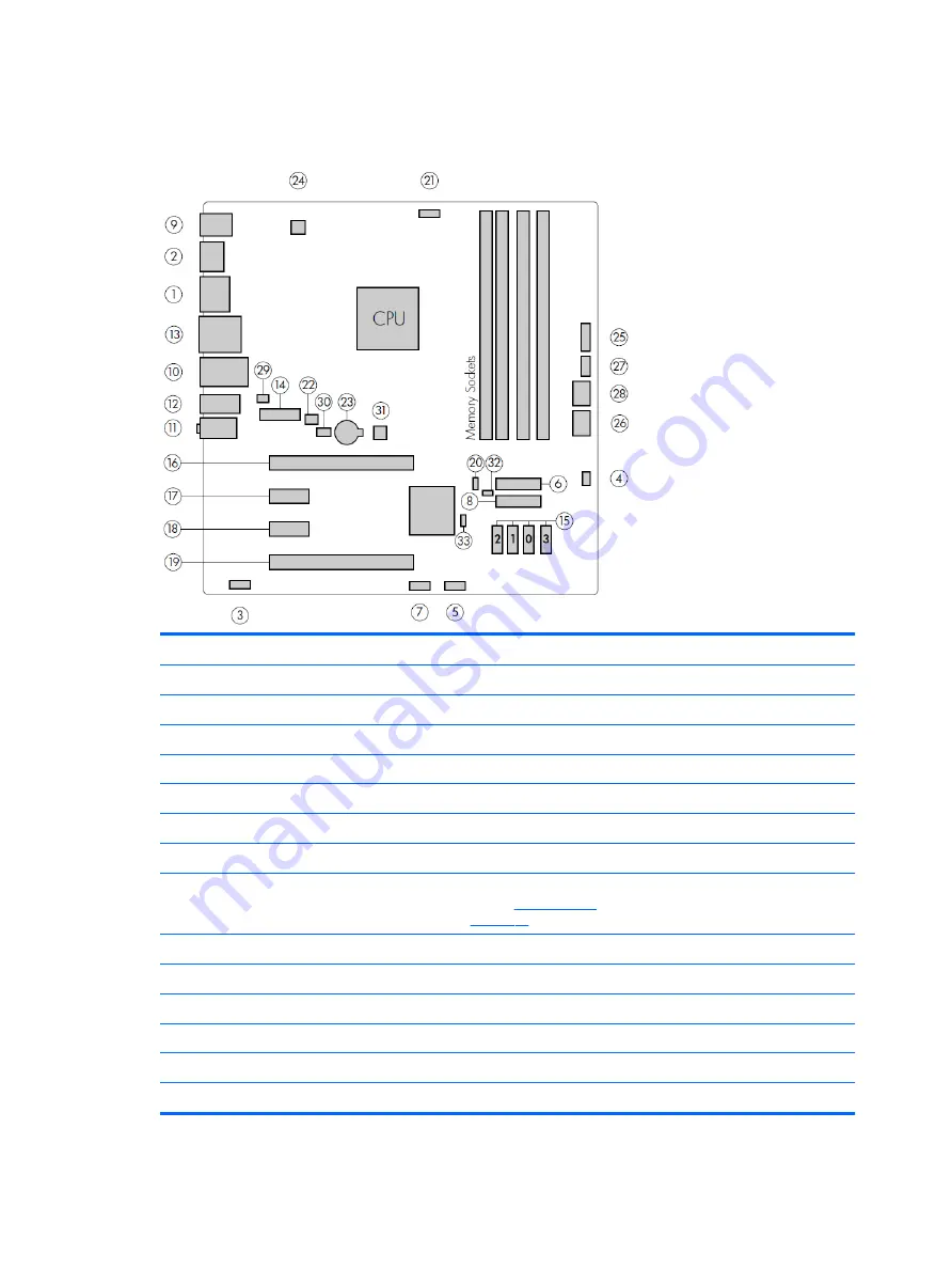
The following illustration and table identify the system board components for the workstation.

I/O

SATA

Power

1

DisplayPort (dual)

15

AHCI 6Gb/s

23

Battery

2

DisplayPort (single)

PCI/PCIe

24

Processor power

3

Front audio

16

PCIe3 x16

25

Front power button/LED

4

Front speaker

17

PCIe3 x1

26

Main power

5

Front USB 2.0

18

PCIe3 x1

27

Power COMM

6

Front USB 3.0

19

PCIe3 x16 (4)

28

SATA power

7

Internal USB 2.0

20

Z turbo drive LED (E19)

Security

8

Internal USB 3.0

NOTE:

For related expansion card 

slot information, see 

Expansion slots 

on page 41

29

Chassis solenoid lock

9

Keyboard/mouse

Cooling

30

Hood sensor

10

Network/rear USB 3.0

21

Processor fan

Service

11

Rear audio

22

Rear fan

31

Clear CMOS button

12

Rear USB 3.0


32

ME/AMT flash override

13

Serial


33

Password jumper

14

Header for serial adapter


HP Z238 Workstation components

5

Summary of Contents for Z238

Page 1: ...HP Z238 Workstation Maintenance and Service Guide ...

Page 2: ...es are available in all editions of Windows This computer may require upgraded and or separately purchased hardware drivers and or software to take full advantage of Windows functionality See http www microsoft com for details Trademark Credits ENERGY STAR is a registered trademark owned by the U S Environmental Protection Agency EPA Intel Core Pentium and Xeon are trademarks are trademarks of Int...

Page 3: ...http www hp com go sml Guide topics Hardware overview on page 1 System management on page 10 Component replacement information and guidelines on page 35 Diagnostics and troubleshooting on page 48 Configuring password security and resetting CMOS on page 70 Configuring RAID devices on page 76 System board designators on page 80 NOTE View the HP Workstation User Guide for your workstation at http www...

Page 4: ...iv About this guide ...

Page 5: ...mode 10 Hyper Threading Technology HTT 11 SATA Power Management 11 Intel Turbo Boost Technology 11 BIOS ROM 11 Computer Setup F10 utilities 12 Using Computer Setup F10 utilities 12 Computer Setup Main 14 Computer Setup Security 16 Computer Setup Advanced 18 Desktop management 23 Initial computer configuration and deployment 24 Installing a remote system 24 Copying a setup configuration to another ...

Page 6: ...ional 33 Side access panel solenoid lock 33 Cable lock optional 33 Fault notification and recovery 33 ECC fault prediction 34 Thermal sensors 34 Programmable power button Windows only 34 Changing the power button configuration Windows only 34 3 Component replacement information and guidelines 35 Warnings and cautions 36 Service considerations 36 Tools and software requirements 36 Electrostatic dis...

Page 7: ...troubleshooting 48 Contacting support 48 Locating ID labels 49 Locating warranty information 49 Diagnosis guidelines 49 Diagnosis at startup 49 Diagnosis during operation 50 Troubleshooting checklist 50 HP troubleshooting resources and tools 51 Online support 51 HP Support Center 51 HP Chat Support 51 Customer Advisories Customer and Security Bulletins and Customer Notices 51 Product Change Notifi...

Page 8: ...esetting the password jumper 70 Clearing and resetting the BIOS 71 Appendix A Linux technical notes 73 System RAM 73 Audio 73 Network cards 74 Hyper Threading Technology 74 NVIDIA Graphics Workstations 74 AMD Graphics Workstations 75 Appendix B Configuring RAID devices 76 RAID hard drive maximum and associated storage controller options 76 Supported RAID configurations 77 Configuring Intel SATA RA...

Page 9: ...rdware overview This chapter presents an overview of workstation hardware components Topics HP Z238 Workstation components on page 2 Product specifications on page 8 Ensuring proper ventilation on page 9 1 ...

Page 10: ...es and components for the computer see http partsurfer hp com Front panel 1 Optional optical disc drive not shown 6 USB 3 0 ports SuperSpeed 2 2 Power button 7 Headphone jack 3 Hard disk drive activity light 8 Headphone microphone combo jack 4 USB 2 0 port 1 charging 9 Optional media card reader shown 5 USB 2 0 port 1 2 Chapter 1 Hardware overview ...

Page 11: ... connectors use industry standard icons and colors NOTE The DP ports are not supported when the system is configured with Intel Xeon E3 12x0 v5 processors Also if a discrete graphics card is installed these ports are disabled by default NOTE Simultaneous usage of integrated Intel HD graphics and discrete graphics cards in order to drive more than two displays can be enabled using the Computer F10 ...

Page 12: ...mponents of a typical workstation layout Drive configurations can vary Item Description Item Description 1 Power supply 5 Chassis 2 Side access panel 6 Slim optical drive 3 Cooler heat sink 7 Hard drive 4 System board 8 Front bezel 4 Chapter 1 Hardware overview ...

Page 13: ...ont USB 2 0 18 PCIe3 x1 27 Power COMM 6 Front USB 3 0 19 PCIe3 x16 4 28 SATA power 7 Internal USB 2 0 20 Z turbo drive LED E19 Security 8 Internal USB 3 0 NOTE For related expansion card slot information see Expansion slots on page 41 29 Chassis solenoid lock 9 Keyboard mouse Cooling 30 Hood sensor 10 Network rear USB 3 0 21 Processor fan Service 11 Rear audio 22 Rear fan 31 Clear CMOS button 12 R...

Page 14: ...rs indicate the mechanical connector size and number of electrical PCIe lanes routed to an expansion slot For example x16 4 means that the expansion slot is mechanically a x16 length connector with 4 PCIe lanes supported 6 Chapter 1 Hardware overview ...

Page 15: ...IMM Graphics cards Up to PCIe Gen 3 bus speeds PCIe x16 cards are supported in the x16 slot closest to the processor Up to three displays with integrated Intel HD graphics depending on processor type Windows 10 supports display output from both integrated graphics capable processors and discrete graphics cards This feature can be changed through the Computer Setup F10 Utility NOTE Most supported I...

Page 16: ...th 35 6 cm 14 1 in Environmental specifications Characteristic Z238 Workstation Temperature Operating 5 C to 35 C 40 F to 95 F Non operating 40 C to 60 C 40 F to 140 F NOTE Derate by 1 C 1 8 F for every 305 m 1 000 ft altitude over 1 524 m 5 000 ft Humidity Operating 8 to 85 relative humidity non condensing Non operating 8 to 90 relative humidity non condensing Altitude Operating 0 to 3 048 m 10 0...

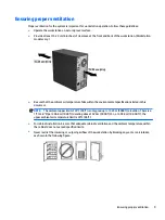
Page 17: ...s listed in this document NOTE The ambient upper limit of 35 C 95 F is only good up to 1524 m 5000 ft elevation There is a 1 C 33 8 F per 304 8 m 1000 ft derating above 1524 m 5000 ft So at 3 048 m 10 000 ft the upper ambient air temperature limit is 30 C 86 F For cabinet installation be sure that adequate cabinet ventilation and the ambient temperature within the cabinet does not exceed specified...

Page 18: ...ndows and search in the Start Menu for the setting Choose what the power buttons do Clear Turn on fast startup recommended If the check box is not available select Change settings that are currently unavailable at the top of the window If using Windows 10 use the taskbar search field to search for Power Options Select Choose what the power button does then select Turn on fast startup recommended D...

Page 19: ...bus and or device power management Intel Turbo Boost Technology Your workstation supports Intel Turbo Boost Technology This feature enables the CPU to run at a higher than normal rate When all CPU cores are not necessary for the workload inactive cores are turned off and power is diverted to the active cores to increase their performance Turbo Boost is enabled and disabled with Computer Setup F10 ...

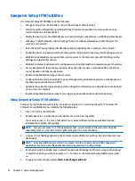
Page 20: ...d in Setup and POST Replicate the system setup by saving system configuration information on a USB device and restoring it on one or more computers Enable or disable DriveLock security or securely erase a hard drive when supported by drive Using Computer Setup F10 utilities Computer Setup can be accessed only by turning the computer on or restarting the system To access the Computer Setup Utilitie...

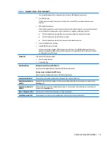
Page 21: ...s have been saved then factory defaults are used NOTE Settings in the Security menu are not modified by Apply Defaults Those values are reset by Restore Security Settings to Factory Defaults at the bottom of the Security menu NOTE Not all settings shown in the following sections are available for all models CAUTION Do NOT turn the computer power OFF while the BIOS is saving the Computer Setup F10 ...

Page 22: ...rsion Super I O Firmware version Born On Date Serial Number SKU number UUID Universally Unique Identifier Asset Tracking Number Feature Byte Build ID Product Family System Board ID System Board CT Integrated MAC Address System Diagnostics If the hard drive has the HP Advanced Diagnostics installed the application will launch If HP Advanced Diagnostics is not installed then a basic version built in...

Page 23: ... Softpaqs at www hp com will copy the BIOS file to the correct location on the hard drive or USB device System IDs Lets you set the following values Asset Tracking Number Ownership Tag Replicated Setup Backup current settings to USB device Saves system configuration to a formatted USB flash media device Restore current settings from USB device Restores system configuration from a USB flash media d...

Page 24: ...licies Lets you set the guidelines for a valid password Options include Password minimum length Requires at least one symbol Requires at least one number Requires at least one upper case character Requires at least one lower case character Allows spaces Clear Password Jumper Select Honor to allow or Ignore to not allow the absence of the password jumper to clear the passwords at boot up Default is...

Page 25: ... Set DriveLock Master Password Sets the drive s master password but does not enable DriveLock Enable DriveLock Sets the drive s user password and enables DriveLock Secure Erase Lets you select a hard drive to completely erase Once a hard drive has been erased with a program that utilizes Secure Erase firmware commands no file recovery program partition recovery program or other data recovery metho...

Page 26: ... 3 Computer Setup Advanced for advanced users Option Heading Display Language Lets you select the language of the menus in F10 Setup and the keyboard layout Scheduled Power On This feature wakes the system up from a powered off state at a specified date and time Boot Options Select the devices that the computer can boot from as well as other options including Startup Menu Delay sec Enabling this f...

Page 27: ...Legacy Support Lets you turn off all legacy support on the computer including booting to DOS running legacy graphics cards booting to legacy devices and so on Windows 7 for instance requires legacy support whereas Windows 10 does not Secure Boot Lets you make sure an operating system is legitimate before booting to it making Windows resistant to malicious modification from preboot to full OS booti...

Page 28: ...can be set for 15 30 60 90 120 or 180 days The reminder will show during POST after the reminder timer has expired Video Memory Size Use this option to manage graphics memory allocation The value you choose is allocated permanently to graphics and is unavailable to the operating system If a discrete graphics card is installed when Intel graphics is also available then Integrated Video displays ins...

Page 29: ...cy All UEFI All UEFI except video Slot settings Lets you enable or disable any PCIe slot Power Management Options Runtime Power Management enable disable Allows certain operating systems to reduce processor voltage and frequency when the current software load does not require the full capabilities of the processor Default is enabled Extended Idle Power States enable disable Allows certain operatin...

Page 30: ... during remote AMT redirection operations The emulation options allow administrators to select which mode works best with their console Show Unconfigure ME Confirmation Prompt enable disable Default is enabled Verbose Boot Messages enable disable Default is enabled Verbose boot shows additional logging information during the boot mainly for debugging if something goes wrong during bootup Watchdog ...

Page 31: ...naging software on page 25 HP Client Management Solutions on page 25 Altiris Client Management Solutions on page 25 HP SoftPaq Download Manager on page 26 System Software Manager on page 26 ROM Flash on page 26 FailSafe Boot Block on page 26 Workstation security on page 27 Fault notification and recovery on page 33 Programmable power button Windows only on page 34 NOTE Support for specific feature...

Page 32: ...perating system application software or drivers To initiate a remote system installation press f12 when f12 Network Service Boot appears in the lower right corner of the HP logo screen Follow the on screen instructions to continue the installation process The default boot order is a BIOS configuration setting that can be changed to always attempt a network boot Copying a setup configuration to ano...

Page 33: ...tworked environment HP Client Management Solutions offers these services Detailed views of hardware inventory for asset management PC health check monitoring and diagnostics Proactive notification of changes in the hardware environment Web accessible reporting of business critical details such as thermal warnings and memory alerts Remote updating of system software such as device drivers and ROM B...

Page 34: ...om modifying the BIOS settings To upgrade the BIOS download the latest SoftPaq images from http www hp com support workstation_swdrivers Remote ROM Flash Remote ROM Flash allows system administrators to safely upgrade the ROM on remote HP computers from a centralized network management console resulting in a consistent deployment of and greater control over HP PC ROM images over the network To use...

Page 35: ...ction provides information about providing system security through asset tracking password security hard drive locking and chassis locks Asset tracking Asset tracking features provide asset tracking data that can be managed using HP Systems Insight Manager HP SIM HP Console Management Controller CMC or other systems management applications Seamless automatic integration between asset tracking feat...

Page 36: ...s for whom data security is a paramount concern For such customers the cost of a hard drive and the loss of the data stored on it is inconsequential when compared to the damage that could result from unauthorized access to its contents To balance this level of security with the need to address the issue of a forgotten password the HP implementation of DriveLock employs a two password security sche...

Page 37: ...ble DriveLock or not This gives the administrator the ability to modify DriveLock settings if the drive is locked in the future After the master password is set the system administrator can enable DriveLock or leave it disabled If a locked hard drive is present POST requires a password to unlock the device If a power on password is set and it matches the device s user password POST does not prompt...

Page 38: ...omputer supports two security password features that are established through the Computer Setup Utilities menu Administrator password when you establish only an administrator password any user can access all the information on the computer except Computer Setup Power on password when you establish only a power on password the power on password is required to access Computer Setup and any other inf...

Page 39: ...ttached PS 2 keyboard remains locked until you enter the power on password To enable Network Server Mode you must set a power on password under Security Set Up BIOS Power On Password This option enables the computer to start without requiring the power on password but the keyboard and mouse are locked until you enter the password The keyboard LEDs rotate constantly when the computer is in locked m...

Page 40: ...ear on the screen If you enter the password incorrectly a broken key icon appears Try again After three unsuccessful tries you must restart the computer before you can continue National keyboard delimiter characters Each keyboard meets country specific requirements The syntax and keys you use for changing or deleting passwords depend on the keyboard included with the computer Language Delimiter La...

Page 41: ...u must restart the computer and then press and hold the F10 key again to access Computer Setup F10 Utility If you are using a PS 2 keyboard you might see a keyboard error message Disregard it 3 Select Security Smart Cover Cover Removal Sensor and follow the on screen instructions 4 Before exiting select Main Save Changes and Exit Side access panel solenoid lock The side access panel solenoid lock ...

Page 42: ...mize the behavior of the power button so that rather than powering down the workstation enters sleep mode low power state or hibernate mode very low power state This lets you go to standby without closing applications and then return to the same operational state without any data loss Changing the power button configuration Windows only Windows 7 or Windows 10 1 Select Start and then select Contro...

Page 43: ... step by step procedures IMPORTANT Removal and replacement procedures are now available in videos on the HP website Go to the HP Customer Self Repair Services Media Library at http www hp com go sml This chapter includes these topics Topics Warnings and cautions on page 36 Service considerations on page 36 Product recycling on page 38 Component replacement guidelines on page 38 35 ...

Page 44: ... Do not use the front bezel as a handle or lifting point when lifting or moving the computer Lifting the computer from the front bezel or lifting it incorrectly might cause the computer to fall causing possible injury to you and damage to the computer To properly and safely lift the computer lift from the bottom of the computer CAUTION Static electricity can damage the electronic components of the...

Page 45: ...ded metal object Avoid contact with pins leads or circuitry Place reusable electrostatic sensitive parts from assemblies in protective packaging or nonconductive foam Personal grounding methods and equipment Use the following items to help prevent ESD damage Wrist straps These are flexible straps with a maximum of one megohm 10 resistance in the ground cords To provide a proper ground wear the str...

Page 46: ...ding bags Transparent shielding tubes Product recycling HP encourages customers to recycle used electronic hardware HP original print cartridges and rechargeable batteries For information about recycling HP components or products see http www hp com go recycle Component replacement guidelines This section provides information and guidelines for removal and replacement procedures It does not docume...

Page 47: ...ts being removed or replaced Keep cables away from direct contact with major heat sources such as the heatsink Some air flow guides have a cable guide that lets you route cables safely around the heatsink Do not jam cables on top of expansion cards or DIMMs Circuit cards and DIMMs are not designed to take excessive pressure Keep cables clear of movable or rotating parts such as the power supply an...

Page 48: ...fully tighten one screw and then move on to the next Instead tighten all screws a little at a time ensuring that the CPU remains level CAUTION Observe the following cautions when removing or replacing the CPU Internal components might be powered even when the computer is off To prevent damage disconnect the computer power cord before you remove or install a component The CPU socket contacts and pa...

Page 49: ...slot for the graphics card only cards certified as After Market Options are supported Install a card in a slot that most closely matches its interface technology Install a PCIe Gen1 x16 or a PCIe Gen1 x8 card in the PCIe Gen3 x16 slot Install a PCIe Gen1 x4 card in the PCIe Gen2 x4 slot Install a PCIe Gen1 x1 card in the PCIe Gen2 x1 slot Install a PCI card in the PCI slot Whenever possible instal...

Page 50: ...ility 4 PCIe3x16 4 x16 x4 3 PCIe3x1 x1 x1 2 PCIe3x1 x1 x1 1 PCIe3 x16 x16 x16 NOTE The PCIe designators indicate the mechanical connector size and number of electrical PCIe lanes routed to an expansion slot For example x16 4 means that the expansion slot is mechanically a x16 length connector with 4 PCIe3 lanes supported Slot one is the graphics slot 42 Chapter 3 Component replacement information ...

Page 51: ...connector Handle a drive carefully Do not drop it from any height To prevent possible ESD damage when the drive is installed connect the drive power cable before connecting the data cable This discharges accumulated static electricity through the drive power cable to the computer chassis Do not use excessive force when inserting a drive Avoid exposing a hard drive to liquids temperature extremes o...

Page 52: ...POST the workstation can still be started The warning will indicate the location of the failed DIMM on the system board If there is no way for the BIOS to obtain a valid memory configuration by disabling plugged in memory the BIOS halts with a diagnostics 2006 code for memory error five beeps and blinks DIMM installation guidelines Install only HP approved DDR3 DIMMs CAUTION HP ships only DIMMs th...

Page 53: ...ll DIMMs in this order NOTE If you install DIMMs of different sizes load them in order of size starting with largest and finishing with the smallest largest in DIMM 1 smallest in last loaded DIMM Component replacement guidelines 45 ...

Page 54: ...issipation specifications are available for multiple configurations To review available specifications go to http www hp com go quickspecs To reach zero power consumption unplug the workstation from the power outlet or use a power strip with an on off switch For additional information about power saving features see the operating system installation instructions This product is in compliance with ...

Page 55: ...tem board connectors Cable To Cable designator on system board PSU cable PCA Main power P1 White PSU cable PCA PWR COMM P2 White PSU cable PCA CPU power P3 White SATA power cable PCA P160 Black SATA power cable ODD P12 Black SATA power cable Second HDD P20 Black SATA power cable First HDD P30 Black Speaker PCA P6 White Cooler fan cable PCA P8 White System fan cable PCA P11 Brown Front audio cable ...

Page 56: ...umbers model names and model numbers and have them in front of you Note any applicable error messages Note any add on options Note the operating system Note any third party hardware or software Note the details of any blinking LEDs on the front of the workstation Note the applications you were using when you encountered the problem NOTE When contacting HP for service or support you might be asked ...

Page 57: ...roduct warranty go to http h20565 www2 hp com hpsc wc public home and make your selection from the Related Links HP Care Pack Services offer upgraded service levels to extend and expand a standard product warranty Diagnosis guidelines If you encounter a problem with the computer monitor or software the following sections provide a list of general suggestions that help you isolate and focus on the ...

Page 58: ...ou are working on a network plug another computer with a different cable into the network connection There might be a problem with the network plug or cable If you recently added new hardware remove the hardware and verify if the computer functions properly If you recently installed new software uninstall the software and verify if the computer functions properly If the screen is blank plug the mo...

Page 59: ...complete the following steps 1 Go to http www hp com go workstationsupport 2 Search for your product HP Chat Support HP Chat Support is a set of web based support tools that automate and speed up the resolution of problems concerning desktop computing tape storage and printing HP Chat Support enables you to electronically submit a support ticket to HP over the web When you submit a support ticket ...

Page 60: ... a functional AC outlet Verify that the monitor is on and the green monitor light is on If the monitor is dim turn up the brightness and contrast controls During operation Beeps and blinking lights on the workstation are error codes that can help you diagnose problems For more information on interpreting these codes see the Diagnostic LED and audible beep codes section in the Maintenance and Servi...

Page 61: ...Customer Self Repair Under the Customer Self Repair programs you can order a replacement part and install the part without on site HP technical assistance Customer Self Repair might be required for some components For more information go to http www hp com go selfrepair and select your product NOTE Some components are not eligible for Customer Self Repair and must be returned to HP for service Cal...

Page 62: ...led or enabled in Computer Setup F10 Utility Poor performance is experienced Processor is hot 1 Verify that airflow to the computer is not blocked 2 Verify that chassis fans are connected and working properly Some fans operate only when needed 3 Verify that the processor heatsink is installed properly Hard drive is full Transfer data from the hard drive to create more space on the hard drive Works...

Page 63: ...identified Improper cable connection On computers with discrete data and power cables make sure that the data and power cables are securely connected to the hard drive See the Hard drive section of this guide for connection details Improperly seated hard drive On systems with blind mate drive connections check for connector damage on the drive and in the chassis Reseat the hard drive and its carri...

Page 64: ...ility and enable the hard drive entry in the Advanced Boot Options list Workstation will not start Hard drive is damaged Replace the hard drive Solving printer problems Problem Cause Solution Printer does not print Printer is not turned on and online Turn the printer on and be sure it is online The correct printer driver for the application is not installed 1 Install the correct printer driver for...

Page 65: ...et the resolution The display works properly during the POST but goes blank when the operating system starts The display settings in the operating system are incompatible with your graphics card and monitor 1 For Windows restart your computer in VGA mode 2 After the operating system starts change the display settings to match those supported by your graphics card and monitor 3 Refer to your operat...

Page 66: ...lays have been activated inside the monitor None It is normal for some monitors to make a clicking noise when turned on and off when going in and out of Standby mode and when changing resolutions High pitched noise coming from inside a flat panel monitor Brightness and contrast settings are too high Lower brightness and contrast settings Fuzzy focus streaking ghosting or shadowing effects horizont...

Page 67: ...ute check box Computer is in Standby mode Press the power button to resume from Standby mode Noise or no sound comes out of the speakers or headphones 1 If you are using digital speakers that have a stereo jack and you want the system to autoswitch to digital use a stereo to mono adapter to engage the auto sense feature or use multimedia device properties to switch the audio signal from analog to ...

Page 68: ... fan spins If the heatsink fan is not spinning verify that the fan cable is plugged into the system board connector Verify that the fan is properly seated 5 Replace the processor heatsink Power LED flashes red once every 2 seconds Power failure power supply is overloaded 1 Determine whether a device is causing the problem by performing the following a Disconnect AC power b Remove all attached devi...

Page 69: ... To download the HP PC Hardware Diagnostics UEFI tool to a USB drive see Downloading HP PC Hardware Diagnostics UEFI to a USB device on page 61 b Hard drive c BIOS 3 When the diagnostic tool opens select the type of diagnostic test you want to run and then follow the on screen instructions NOTE If you need to stop a diagnostic test press esc Downloading HP PC Hardware Diagnostics UEFI to a USB dev...

Page 70: ...ext messages If a POST error occurs the screen will display the error message To manually switch to the POST Messages Enabled mode during POST press any key except F10 F11 or F12 The default mode is POST Message Disabled The speed at which the computer loads the operating system and the extent to which it is tested are determined by the POST mode selection Quick Boot is a fast startup process that...

Page 71: ...If the problem persists replace the RTC battery See the Removal and Replacement section for instructions on installing a new battery 008 Microcode Patch Error Processor is not supported by the BIOS 1 Upgrade BIOS to proper version 2 Change the processor 009 PMM Allocation Error during MEBx Download Memory error during POST execution of the Management Engine ME BIOS Extensions option ROM 1 Reboot t...

Page 72: ...1 Reboot the computer 2 If the error persists update to the latest BIOS version 3 If the error still persists replace the system board 00F Interface Error during MEBx Execution MEBx operation experienced a hardware error during communication with the ME 1 Reboot the computer 2 If the error persists update to the latest BIOS version 3 If the error still persists replace the system board 100 Front A...

Page 73: ...gnostics when booting the computer 2 Apply hard drive firmware patch if applicable Available at http www hp com support 3 Back up contents and replace hard drive 302 Hard Disk 2 SMART Hard Drive Detects Imminent Failure Hard drive is about to fail Some hard drives have a hard drive firmware patch that will fix an erroneous error message 1 Determine if hard drive is giving correct error message Run...

Page 74: ...r Setup or Windows utilities 419 Out of Memory Space for Option ROMs Recently added PCI expansion card contains an option ROM too large to download during POST If a PCI expansion card was recently added remove it to see if the problem remains 41A Front USB1 USB2 Not Connected Front USB cable has been detached or unseated from system board Reconnect or replace front USB cable 41B Device in PCI Expr...

Page 75: ...1 ports should be used for hard drives before other ports Ensure SATA connectors are used in ascending order For one device use SATA 0 For two devices use SATA 0 and SATA 1 For three devices use SATA 0 SATA 1 and SATA 2 90B Fan Failure The system has detected that a cooling fan is not operating correctly 1 Reseat fan 2 Reseat fan cable 3 Replace fan 90D System Temperature Thermal shutdown occurred...

Page 76: ...ink codes are not used Number of long beeps blinks Error category 1 Not used 2 BIOS 3 Hardware 4 Thermal 5 System board Patterns of blink beep codes are determined by using the following parameters 1 second pause occurs after the last major blink 2 second pause occurs after the last minor blink Beep error code sequences occur for the first 5 iterations of the pattern and then stop Blink error code...

Page 77: ...support an enabled feature Thermal 4 2 A processor over temperature condition has been detected 4 3 An ambient temperature over temperature condition has been detected 4 4 An MXM over temperature condition has been detected System board 5 2 The embedded controller cannot find valid firmware 5 3 The embedded controller has timed out waiting for the BIOS 5 4 The embedded controller has timed out wai...

Page 78: ...p your computer CMOS settings Pressing the Clear CMOS button resets CMOS values to factory defaults and erases customized information including asset numbers and special settings To back up the CMOS settings run Computer Setup F10 Utility and select Save to Diskette from the File menu Resetting the password jumper CAUTION Stringent security is a mode where there is no physical bypass of the passwo...

Page 79: ... grounded metal object See the Safety Regulatory Information guide for more information 3 Remove the access panel 4 Locate the header and jumper NOTE The password jumper is green so that it can be easily identified 5 Remove the jumper from pins 1 and 2 6 Place the jumper on either pin 1 or 2 but not both so that it does not get lost 7 Replace the access panel and reconnect the external equipment 8...

Page 80: ...y Regulatory Information guide for more information 3 Remove the access panel CAUTION Pushing the CMOS button will reset CMOS values to factory defaults It is important to back up the computer CMOS settings before resetting them in case they are needed later Back up is easily done through Computer Setup See Computer Setup F10 utilities on page 12 for information on backing up the CMOS settings 4 L...

Page 81: ...t amounts of total RAM in various HP workstations based on the number of hardware DIMM slots and the capabilities of the system The total memory supported for each configuration is listed in the Hardware Support Matrix for HP Linux Workstations at http www hp com support linux_hardware_matrix Audio All HP workstations come with built in audio hardware The audio hardware is supported by the Advance...

Page 82: ...TT NOTE On most recent Linux distributions including RHEL 6 SLED 11 and updates to those streams the kernel automatically detects that HTT is enabled and works correctly NVIDIA Graphics Workstations Some workstation configurations come with NVIDIA Quadro graphics hardware HP recommends the use of NVIDIA drivers for best results on Linux systems HP provides recommended versions of the drivers with ...

Page 83: ...with the AMD graphics drivers by claiming the hardware early in the boot process The AMD driver installation process usually blacklists conflicting drivers and turns off kernel mode setting in the initial RAM image Administrator customization of the display characteristics and many other aspects of an AMD graphics driver environment is available through the following command which starts the Catal...

Page 84: ...ion about RAID configuration go to http www hp com support RAID_FAQs RAID hard drive maximum and associated storage controller options This section lists the maximum number of hard drives supported on HP workstations according to RAID configuration and storage controller options NOTE This section applies to internal workstation configurations that do not use add in cards and external enclosures Ha...

Page 85: ... addition to some previous releases If this driver is not available in the distribution or is not applicable to the platform e g the RST controller the Software RAID solution is recommended You can create a SATA RAID array that contains up to the maximum number of internal SATA hard drives and eSATA drives if you use an optional eSATA bulkhead cable supported on your workstation The Intel SATA opt...

Page 86: ...ultiple device offers integrated software RAID without the need for additional hardware disk controllers or kernel patches Unlike most hardware RAID solutions software RAID can be used with all types of disk technologies including SATA SCSI and solid state drives This software solution requires only minimal setup of the disks themselves However when compared to hardware based RAID software RAID ha...

Page 87: ...ce of the performance pipeline is being directly addressed by moving to RAID Configuring software RAID See the following sites for additional information about configuring software RAID Red Hat Enterprise Linux 7 See the Storage Administration Guide at https access redhat com documentation en US Red_Hat_Enterprise_Linux 7 html Storage_Administration_Guide index html Red Hat Enterprise Linux 6 See ...

Page 88: ...ector J68 PS2 Mouse connector stacked over keyboard connector J78 IN OUT Audio line in stacked over audio line out JZ87 88 JZ87 88 Slot1 4 PCIe x16 retention clip SW50 SW50 CMOS Clear CMOS switch push button P1 PWR Power supply 6 pin white P2 PWRCMD Power command 6 pin white P3 PWRCPU Power supply 4 pin white P5 P5 PB LED Front power button LED black P6 SPKR Internal speaker white P8 CPU FAN CPU f...

Page 89: ...creen Component Description P26 FRONT USB3 0 Front I O USB 3 0 blue P160 SATAPWR0 HDD power black XBT1 XBT1 BAT Battery holder XMM1 XMM4 XMM1 XMM4 DIMM1 DIMM4 Memory slots XU1 XU1 CPU socket System board designators 81 ...

Page 90: ...68 messages 63 expansion card slot identification workstation 42 F flashing LEDs 68 front panel components 2 H HP PC Hardware Diagnostics UEFI downloading 61 L links Contact information for HP US 51 HP Chat Support 51 HP Customer Self Repair 53 M Memory DIMM installation guidelines 44 N numeric error codes 63 O Operating system setup 73 P Password configuration 70 Power supply Expansion card confi...

Page 91: ...stions at startup 52 suggestions during operation 52 Troubleshooting 48 troubleshooting locating ID labels 49 locating warranty info 49 more options 53 resources and tools 51 U urls Contact information for HP US 51 HP Chat Support 51 HP Customer Self Repair 53 W weights and dimensions 8 Workstation setup Ensuring proper ventilation 9 Index 83 ...

Reviews: