background image

Issuing System Commands

3-10

upload

upload

upload

upload

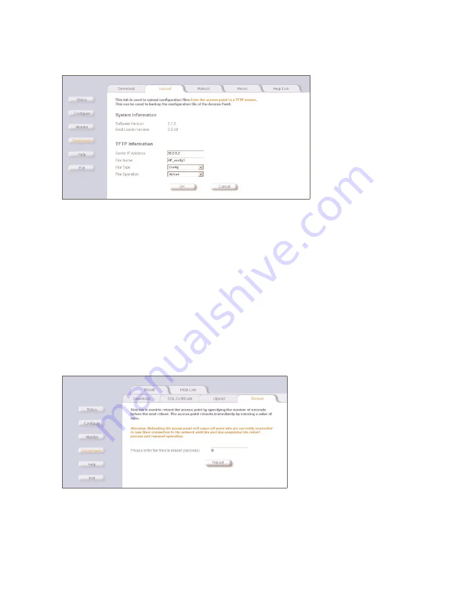
Figure 3-14

Figure 3-14

Figure 3-14

Figure 3-14  Command Screens - Upload

 Command Screens - Upload

 Command Screens - Upload

 Command Screens - Upload

Use the 

Upload

Upload

Upload

Upload

 tab to upload Configuration files from the WL520. The TFTP server must be running, and configured to point to 

the directory that is to contain the uploaded file. We suggest you assign the file a meaningful name, which may include version 

or location information.
If you don’t have a TFTP server installed on your system, install the TFTP server from the CD. Select the “Xtras/SolarWinds” 

sub-directory, double-click “OEM-TFTP-Server.exe”, and follow the directions given to complete the installation.

Server IP Address

Server IP Address

Server IP Address

Server IP Address

. Enter the TFTP server IP Address.

Double-click on the TFTP server icon on your desktop and locate the IP address assigned to the TFTP server. Note: This is 

the IP address that will be used to point the Access Point to the AP Image file.

File Name

File Name

File Name

File Name

. Enter the name of the file to be uploaded. 

Copy the updated AP Image file to the shared TFTP server folder. The default AP Image is located at C:/Program Files/

WL520_AP/AP/.

File Type

File Type

File Type

File Type

. Select 

Config

Config

Config

Config

File Operation

File Operation

File Operation

File Operation

. Select 

Upload

Upload

Upload

Upload

reboot

reboot

reboot

reboot

Figure 3-15

Figure 3-15

Figure 3-15

Figure 3-15  Command Screens - Reboot

 Command Screens - Reboot

 Command Screens - Reboot

 Command Screens - Reboot

Use the 

Reboot

Reboot

Reboot

Reboot

 tab to save configuration changes (if any) and reset the WL520. Entering a value of 0 (zero) seconds causes an 

immediate reboot. Note that 

Reset

Reset

Reset

Reset

, covered below, does not save configuration changes.

Summary of Contents for WL520

Page 1: ...e wl520 unit using the web interface 2 3 set system name location and contact information 2 5 set a static ip address for the wl520 device 2 5 set network names 2 6 set wep encryption for each wireless interface 2 7 set and change passwords 2 8 download the latest software 2 9 setup your tftp server 2 9 download updates from your tftp server 2 9 backup your wl520 configuration file 2 10 copy a con...

Page 2: ... 2 21 mac access control via radius 2 21 ieee 802 1x security mode 2 23 authentication process 2 23 configuring security settings 2 24 802 1x security and wireless distribution systems wds 2 25 if you encounter problems 2 25 agi t e hp wl520 3 managing the hp wl520 management interface 3 2 monitoring network statistics 3 3 view hardware software component information 3 3 monitoring icmp statistics...

Page 3: ...vice interfaces 4 10 setting filters 4 11 setting the ethernet protocol filter 4 11 advanced filtering 4 12 tcp udp port filtering 4 12 adding tcp udp port filters 4 13 editing tcp udp port filters 4 14 alarms snmp traps 4 14 alarm trap groups 4 14 alarm host table 4 14 syslog 4 15 setting syslog event notifications 4 15 enabling syslog event notifications 4 15 bridge configuration settings 4 16 m...

Page 4: ...rk 5 2 basic software setup and configuration problems 5 2 lost wl520 telnet or snmp password 5 2 client computer cannot connect 5 3 wl520 has incorrect ip address 5 3 http browser or telnet interface does not work 5 3 html help files do not appear 5 3 telnet cli does not work 5 3 tftp server does not work 5 3 client connection problems 5 4 client software finds no connection 5 4 client pc card do...

Page 5: ...93 alarms 5 8 related applications 5 9 radius authentication server 5 9 tftp server 5 9 led indicators 5 9 6 using the command line interface prerequisite skills and knowledge 6 1 notation conventions 6 1 important terminology 6 2 navigation and special keys 6 2 cli error messages 6 2 command line interface cli variations 6 3 bootloader cli 6 3 cli command types 6 4 operational cli commands 6 4 li...

Page 6: ...ble vlan management 6 17 change your wireless interface settings 6 18 enable disable closed system 6 18 enable disable load balancing 6 18 enable disable medium density distribution 6 18 autochannel select acs 6 18 set the distance between aps 6 19 set the multicast rate 6 19 set ethernet speed and transmission mode 6 19 set interface management services 6 19 configure mac access control 6 20 set ...

Page 7: ...ort filtering 6 35 syslog parameters 6 35 iapp parameters 6 36 spectralink voip parameters 6 36 bridging parameters 6 37 static mac address filter table 6 37 spanning tree parameters 6 37 storm threshold parameters 6 38 intra bss subscriber blocking 6 38 packet forwarding parameters 6 38 cli monitoring parameters 6 39 7 recording your configuration settings c your conf n setting configuration sett...

Page 8: ...in the same subnet To determine the best location for the Base Station units we recommend conducting a Site Survey before placing the devices in their final locations For information about how to conduct a Site Survey contact your local reseller Before the WL520 unit can be configured for your specific networking requirements it must first be initialized Initialization consists of setting a static...

Page 9: ...ss file name and file type parameters Q If necessary use the CLI with your computer serial port to initialize the proper IP address for your network Q The CLI provides configuration and management access for most generic Telnet and Terminal clients Use the CLI through your computer serial port over your LAN through the Internet or with a crossover Ethernet cable connected directly to your computer...

Page 10: ...fferent for the 2 4 GHz band and the 5 GHz band The table below compares the software features supported for each type of card in the WL520 device fe feature 2 4 ghz 802 11b 5 ghz 802 11a comments Number of stations per BSS up to 250 up to 50 HTTP Server yes yes Telnet CLI yes yes SNMP Agent yes yes VLAN Support 2 User VLANs yes yes Emergency Reset to Default Configuration yes yes DHCP Client yes ...

Page 11: ...ect a channel for products sold in Europe these products require automatic channel selection using DFS See Dynamic Frequency Selection DFS Frequency Channel 1 2 412 GHz 2 2 417 GHz 3 2 422 GHz default FCC ETSI Japan 4 2 427 GHz 5 2 432 GHz 6 2 437 GHz 7 2 422 GHz 8 2 447 GHz 9 2 452 GHz 10 2 457 GHz 11 2 462 GHz 12 2 467 GHz ETSI countries only 13 2 472 GHz 14 2 477 GHz Japan only For France chann...

Page 12: ...ec 2 Mbits sec default 5 5 Mbits sec 11 Mbits sec Available options depend on Distance Between APs setting N A Interference Robustness Enable default Disable N A Closed System Enable Disable default N A Load Balancing Enable default Disable N A Medium Density Distribution Enable default Disable N A cell size and coverage area The coverage area achieved with the 2 4 GHz card type is larger than tha...

Page 13: ...11a versus 802 11b Coverage Area installation and initialization The WL520 is designed to support both 2 4 GHz IEEE 802 11b radio cards and 5 GHz IEEE 802 11a radio cards The hp WL520 AP 5 GHz kit for the WL520 has an antenna adapter which snaps into place on the existing wall mounting bracket Refer to the printed Quick Start Guide provided in you kit for instructions on installing the Base Statio...

Page 14: ...e suggest you accept the default values Q Prerequisites Q ScanTool Program Q Set Basic Configuration Parameters Q Download the Latest Software Setup your TFTP Server Download Updates from your TFTP Server Backup your WL520 Configuration File Copy a Configuration File from Another WL520 Unit Q Other Network Settings Configure the WL520 Device as a DHCP Server Maintain 802 11b Client Connections usi...

Page 15: ...er IP Address The network administrator typically provides this IP Address NOTE Configuration software comes with the WL110 PC Cards used in wireless client computers The current network profile on the wireless client must contain a valid Network Name in other words one of the case sensitive Network Names defined in the WL520 s WL110 PC Card Wireless Interface properties For more information pleas...

Page 16: ...m the following operations Note that certain options are available only when selecting Static IP Address mode MAC Address This read only field displays the MAC Address of the selected unit Name Enter the System Name of the unit This is typically descriptive text such as Main Lobby IP Address Type Select Static if you wish to enter the IP values manually Select DH DHCP to force the unit to request ...

Page 17: ... screen allows you to select options or enter edit and delete information In some cases the WL520 reminds you that it must be rebooted for a change to take effect In a given session you can wait to reboot until all changes have been made After entering or editing information on configuration screens click OK to save K changes or click Cancel to restore previous settings a el You will want to set u...

Page 18: ...ess for the wl520 device Figure 2 6 Figure 2 6 Figure 2 6 N work IP Configuration Network IP Configuration Network IP Configuration set system name location and contact information Figure 2 5 System Configuration Sys io 1 In the Web Interface click the Configure button and select the System tab 2 Enter the name of the WL520 device its location within your network or its physical location such as F...

Page 19: ...he WL520 unit will need to be rebooted for the changes to take effect See Maintain 802 11b Client Connections using Link Integrity and Configuring Advanced Features for information on the other Network features set network names Client stations use the Network Name of the PC Card to connect to the network through the WL520 unit At power up or insertion of either a 2 4 GHz or 5 GHz radio card the W...

Page 20: ... PC Cards in wireless Slots A and or B in the WL520 device K 4 Select OK set wep encryption for each wireless interface Figure 2 8 WEP Encryption EP En 1 In the Web Interface click the Configure button and select the Security tab NOTE If you want to use 802 1x security see IEEE 802 1x Security Mode 2 Select the Encryption sub tab 3 Click the check box to enable Encryption WEP on a wireless card 4 ...

Page 21: ...to use for WEP encryption NOTE Client stations must have the same encryption key to be able to communicate with the WL520 device 6 For 802 11b only set Deny Non Encrypted Data to Enable if you want to prevent clients that do not have WEP enabled and the proper keys configured from communicating with the network 7 Select OK See Change your Wireless Interface Settings for information on the rest of ...

Page 22: ... the proper TFTP server IP Address the proper AP Image file name and that the TFTP server is connected Q Make sure the TFTP server is configured to both Transmit and Receive files with no automatic shutdown or Make sure the TFTP server is configured to both Transmit and Receive files with no automatic shutdown or Make sure the TFTP server is configured to both Transmit and Receive files with no au...

Page 23: ... file to other WL520 units CAUTION Do not use a static IP address in this configuration file otherwise you will end up with duplicate IP addresses in your network 1 Check to ensure Dynamic IP address is enabled by clicking the Configure Configure Configure Configure button and selecting the IPConfig tab 2 In the Web Interface click the Commands Commands Commands Commands button and select the Uplo...

Page 24: ...e network and do not enable the DHCP server without checking with your network administrator first as it could bring down the whole network Use DHCP configuration to provide dynamic client IP Addresses from one or more IP Pool Tables Enable the DHCP Server to allow the WL520 to assign clients IP Addresses from IP Pool Tables Deselect the Status check box to prevent client IP Address assignment fro...

Page 25: ...nections using link integrity maintain 802 11b client connections using link integrity NOTE This feature is only applicable to 2 4 GHz 802 11b cards The Link Integrity feature checks the link between the WL520 and the nodes on the backbone These nodes are listed by their IP address on the Link Integrity IP Address Table and serve as backup If the link goes down the client will connect to another W...

Page 26: ...hines to connect using the client configuration software Range is 1 31 characters default is My Wireless Network A for card in Slot A and My Wireless Network B for card in Slot B Enable Auto Channel Select ACS Enable Auto Channel Select ACS Enable Auto Channel Select ACS Enable Auto Channel Select ACS By default this feature is enabled The WL520 device scans the area for other WL520 devices and se...

Page 27: ... Network Name Enter a Network Name for each PC Card This is the same name used on client machines to connect using the client configuration software Range is 1 31 characters default is My Wireless Network A for card in Slot A and My Wireless Network B for card in Slot B Enable Auto Channel Select ACS Enable Auto Channel Select ACS Enable Auto Channel Select ACS Enable Auto Channel Select ACS By de...

Page 28: ... Density Distribution Enable Medium Density Distribution Enable Medium Density Distribution Enable Medium Density Distribution Enable this option to automatically notify client stations of roaming thresholds for the nearby APs This feature is only available for 802 11b wireless cards Default is enable auto channel select acs auto channel select acs auto channel select acs auto channel select acs W...

Page 29: ... not a configurable parameter It is always enabled and cannot be disabled Q You cannot manually select an operating channel for 802 11a cards you must let DFS select the channel Q You cannot configure the Enable Auto Channel Select Enable Auto Channel Select Enable Auto Channel Select Enable Auto Channel Select option Within the HTTP interface this option will always appear enabled Q 802 11b cards...

Page 30: ...s Ultra High Density Network set the distance between aps set the distance between aps set the distance between aps set the distance between aps 1 From the Web interface click the Configure Configure Configure Configure button and select the Network Network Network Network tab 2 Select the Interfaces Interfaces Interfaces Interfaces sub tab 3 Select the Wireless Slot Wireless Slot Wireless Slot Wi...

Page 31: ...erage transmit rate The variation between Multicast Rate and Distance Between APs is presented in the following table set the multicast rate set the multicast rate set the multicast rate set the multicast rate 1 From the Web interface click the Configure Configure Configure Configure button and select the Network Network Network Network tab 2 Select the Interfaces Interfaces Interfaces Interfaces ...

Page 32: ...lex selects the best transmission mode for the given configuration The recommended setting is auto speed auto duplex auto speed auto duplex auto speed auto duplex auto speed auto duplex Choose between Q 10 Mbit s half duplex full duplex or auto duplex Q 100 Mbit s half duplex full duplex or auto duplex Q auto speed half duplex auto duplex configure your management interfaces configure your managem...

Page 33: ...terface settings configure serial port interface settings configure serial port interface settings The serial port interface on the WL520 device is enabled at all times You can set the following parameters as needed Baud Rate Baud Rate Baud Rate Baud Rate Select the serial port speed bits per second Choose between 2400 4800 9600 19200 38400 or 57600 the default Baud Rate is 9600 9600 9600 9600 Flo...

Page 34: ...r delete an entry in the mac access control table 1 Click the Edit Edit Edit Edit button in the MAC Access Control Table 2 Select the MAC Address you want to disable or delete 3 Click OK OK OK OK NOTE For larger networks that include multiple WL520 devices you may prefer to maintain this list on a centralized location using the RADIUS Authentication Settings radius authentication settings radius a...

Page 35: ...MAC addresses are listed within the RADIUS server Options include dash delimited dash between each pair of digits xx yy zz aa bb cc colon delimited colon between each pair of digits xx yy zz aa bb cc single dash delimited dash between the sixth and seventh digits xxyyzz aabbcc and no delimiters between pairs of hexadecimal digits xxyyzzaabbcc Server Addressing Format Server Addressing Format Serve...

Page 36: ...S server to determine which EAP types it supports NOTE The WL520 supports the following EAP types when 802 1x Security Mode is set to 802 1x EAP TLS PEAP and EAP TTLS When 802 1x Security Mode is set to Mixed the WL520 supports the following EAP types EAP TLS PEAP EAP TLLS and EAP MD5 MD5 does not support automatic key distribution therefore if you choose this method you need to manually configure...

Page 37: ...alue 900 seconds 15 minutes effectively protects against intrusion without disrupting network activities For detailed configuration steps see Setting Up the WL520 using 802 1x Security Mode 4 Mixed mode with 802 1x and WEP encryption Mixed mode with 802 1x and WEP encryption Mixed mode with 802 1x and WEP encryption Mixed mode with 802 1x and WEP encryption Mixed mode supports both 802 1x and WEP ...

Page 38: ... communicating in the WDS share the same encryption key Key 1 See Wireless Distribution System WDS for more information NOTE WDS is only available for 802 11b cards if you encounter problems if you encounter problems if you encounter problems if you encounter problems Q Cannot Associate with a Network When the client starts it automatically looks for a network If it cannot associate with a network...

Page 39: ... Interface Q Monitoring Network Statistics View Hardware Software Component Information Monitoring ICMP Statistics Monitoring IP ARP Statistics Monitoring Learn Table Statistics Monitoring IAPP Statistics Monitoring RADIUS Server Statistics Monitoring Interfaces Statistics Monitoring Remote Link Test Statistics Q Issuing System Commands Download Upload Reboot Reset Help Link ...

Page 40: ...3 1 Figure 3 1 Figure 3 1 Login to HTTP Interface Login to HTTP Interface Login to HTTP Interface Login to HTTP Interface 1 Open your browser and enter the IP Address in the address bar Press the ENTER ENTER ENTER ENTER key Result The WL520 Login screen appears NOTE Leave the User Name User Name User Name User Name field empty 2 Enter your password in the Password Password Password Password field ...

Page 41: ...are software component information view hardware software component information view hardware software component information Figure 3 3 Figure 3 3 Figure 3 3 Figure 3 3 Hardware Software Component Information Hardware Software Component Information Hardware Software Component Information Hardware Software Component Information From the HTTP interface click the Monitor Monitor Monitor Monitor butto...

Page 42: ...ocol statistics Figure 3 4 Figure 3 4 Figure 3 4 Figure 3 4 ICMP Statistics Screen ICMP Statistics Screen ICMP Statistics Screen ICMP Statistics Screen monitoring ip arp statistics monitoring ip arp statistics monitoring ip arp statistics monitoring ip arp statistics This tab provides information based on the Address Resolution Protocol ARP which relates MAC Address and IP Addresses Figure 3 5 Fig...

Page 43: ...cted There can be up 10 000 entries in the Learn Table Figure 3 6 Figure 3 6 Figure 3 6 Figure 3 6 Learn Table Statistics Screen Learn Table Statistics Screen Learn Table Statistics Screen Learn Table Statistics Screen monitoring iapp statistics monitoring iapp statistics monitoring iapp statistics monitoring iapp statistics This tab displays statistics relating to client handovers and communicati...

Page 44: ...erver statistics This tab provides RADIUS authentication information for both the Primary and Backup RADIUS servers NOTE RADIUS authentication must be enabled for this information to be valid Figure 3 8 Figure 3 8 Figure 3 8 Figure 3 8 RADIUS Server Statistics Screen RADIUS Server Statistics Screen RADIUS Server Statistics Screen RADIUS Server Statistics Screen ...

Page 45: ...monitoring interfaces statistics This tab displays information for the Ethernet interface as well as each WL110 PC Card interface The Operational Status can be up down or testing Figure 3 9 Figure 3 9 Figure 3 9 Figure 3 9 Interface Statistics Screen Interface Statistics Screen Interface Statistics Screen Interface Statistics Screen ...

Page 46: ...z 802 11b clients Figure 3 10 Figure 3 10 Figure 3 10 Figure 3 10 Link Test Screen Link Test Screen Link Test Screen Link Test Screen To find wireless clients connected to the WL520 device click Explore Explore Explore Explore then the Refresh Refresh Refresh Refresh button To test the link quality select a station and then click Link Test Link Test Link Test Link Test Quality is measured in terms...

Page 47: ...tions given to complete the installation The Download Download Download Download tab shows version information and allows you to enter TFTP information as described below Server IP Address Server IP Address Server IP Address Server IP Address Enter the TFTP server IP Address Double click the TFTP server icon on your desktop and locate the IP address assigned to the TFTP server Note This is the IP ...

Page 48: ... server IP Address Double click on the TFTP server icon on your desktop and locate the IP address assigned to the TFTP server Note This is the IP address that will be used to point the Access Point to the AP Image file File Name File Name File Name File Name Enter the name of the file to be uploaded Copy the updated AP Image file to the shared TFTP server folder The default AP Image is located at ...

Page 49: ...ddress a new IP Address must be assigned Also refer to Recovery Procedures help link help link help link help link Figure 3 17 Figure 3 17 Figure 3 17 Figure 3 17 Command Screens Help Link Command Screens Help Link Command Screens Help Link Command Screens Help Link To open Help Help Help Help click the Help Help Help Help button on any display screen During initialization the WL520 on line help f...

Page 50: ...rs Static MAC address filters and other advanced filters Alarms SNMP Traps Q Alarm Trap Groups Q Alarm Host Table Q Syslog Set alarms SNMP Traps including enabling alarm groups and the alarm host table Also configure the Syslog settings Bridge Configuration Settings Q Static MAC Address Filter Q Spanning Tree Protocol Q Broadcast Storms and Storm Thresholds Q Intra BSS Subscriber Blocking Q Packet...

Page 51: ...ion Screen DHCP Server Configuration Screen DHCP Server Configuration Screen DHCP Server Configuration Screen Enable DHCP Server Enable DHCP Server Enable DHCP Server Enable DHCP Server Place a check mark in the box provided to allow the WL520 to assign clients IP Addresses from IP Pool Tables Uncheck the box to prevent client IP Address assignment from the WL520 NOTE You should have at least one ...

Page 52: ... the WL520 and connected network server s If the link goes down then the client will connect to another WL520 in your network that still communicates with the server NOTE This feature is only applicable to 2 4 GHz 802 11b cards Figure 4 2 Figure 4 2 Figure 4 2 Figure 4 2 Link Integrity Configuration Screen Link Integrity Configuration Screen Link Integrity Configuration Screen Link Integrity Confi...

Page 53: ...face cards NIC An Ethernet port on the access point typically connects a wireless cell to a wired backbone They communicate across a VLAN capable switch that reviews packet headers and directs traffic to the appropriate ports On the wired network a RADIUS server authenticates traffic and a DHCP server manages IP addresses Resources like servers and printers may be present and a hub may include mul...

Page 54: ...pical user vlan configurations typical user vlan configurations VLANs segment network traffic into workgroups which enable you to limit broadcast and multicast traffic Workgroups enable clients from different VLANs to access different resources using the same network infrastructure Clients using the same physical network are limited to those resources available to their workgroup The three primary...

Page 55: ...one of the wireless NICs and VLAN is enabled Traffic received from wireless clients members of an untagged VLAN is transmitted as appropriate on either the wired or wireless backbone Untagged User VLANs enable VLANs to coexist on networks with non VLAN capable devices such as legacy servers To configure this scenario set up only one workgroup by configuring one tagged interface and one untagged in...

Page 56: ...en 1 and 4094 5 Set the VLAN UserID VLAN UserID VLAN UserID VLAN UserID for the NIC in Slot B to the same value configured for the NIC in Slot A 6 Place a checkmark in the Enable VLAN Protocol box 7 Configure the wireless client with one of the two Network Names Network Names Network Names Network Names based on VLAN membership typical vlan management id configuration scenarios typical vlan manage...

Page 57: ...N User ID VLAN User ID for the wireless NICs in Slot A and Slot B to values between 1 and 4094 5 Set the VLAN Management ID VLAN Management ID VLAN Management ID VLAN Management ID to a value equivalent to one of the VLAN User IDs 6 Place a checkmark in the Enable VLAN Protocol box CAUTION Once a VLAN Management ID is configured and is equivalent to one of the VLAN User IDs on the WL520 all member...

Page 58: ... IP Mask IP Mask Enter a mask that will act as a filter to limit access to a range of IP Addresses Comment Comment Comment Comment Enter an optional comment such as the station name NOTE The IP mask 255 255 255 255 would authorize the single station defined by the IP Address to configure the Access Point device The Access Point device would ignore commands from any other IP address In contrast the...

Page 59: ... select Disabled to prevent a user from accessing the WL520 device from the Web interface HTTP Port HTTP Port HTTP Port HTTP Port Configure the HTTP port from which you will manage the WL520 device via the Web interface By default the HTTP port is 80 telnet configuration settings telnet configuration settings telnet configuration settings telnet configuration settings Use the Services tab to set t...

Page 60: ...rotocols listed in the Filter Table not filter any of the Ethernet protocols listed in the Filter Table not filter any of the Ethernet protocols listed in the Filter Table Filter Operation Type Filter Operation Type Filter Operation Type Filter Operation Type If set to Passthru Passthru Passthru Passthru only the enabled Ethernet Protocols listed in the Filter Table will pass through the bridge If...

Page 61: ...d filtering protocols can filter in the wireless to Ethernet direction the Ethernet to wireless direction or in both directions Click Edit and use the Status Status Status Status field to Enable or Disable the filter Q Deny IPX RIP Q Deny IPX SAP Q Deny IPX LSP Q Deny IP Broadcasts Q Deny IP Multicasts tcp udp port filtering tcp udp port filtering tcp udp port filtering tcp udp port filtering Port...

Page 62: ...le TCP UDP Port Filter Table click Add Add Add Add Figure 4 13 Figure 4 13 Figure 4 13 Figure 4 13 Adding a Port to the TCP UDP Port Filter Table Adding a Port to the TCP UDP Port Filter Table Adding a Port to the TCP UDP Port Filter Table Adding a Port to the TCP UDP Port Filter Table 5 In the TCP UDP Port Filter Table TCP UDP Port Filter Table TCP UDP Port Filter Table TCP UDP Port Filter Table ...

Page 63: ...e Configuration Alarms Enable Configuration Alarms Enable Configuration Alarms Enable Security Alarms Enable Security Alarms Enable Security Alarms Enable Security Alarms Enable Wireless Alarms Enable Wireless Alarms Enable Wireless Alarms Enable Wireless Alarms Enable Operational Alarms Enable Operational Alarms Enable Operational Alarms Enable Operational Alarms Enable Flash Memory Alarms Enable...

Page 64: ...cations setting syslog event notifications Syslog Events are logged according to the level of detail specified by the administrator Logging only urgent system messages will create a far smaller more easily read log then a log of every event the system encounters Determine which events to log by selecting a priority defined by the following scale event event event event priority priority priority p...

Page 65: ... WL520 unit is connected to your network it learns which devices are connected to it by recording the MAC addresses of each device to which it sends packets during the course of a normal session To view the Learn Table click on the Monitor button in the web interface and select the Learn Table tab The table can hold up to 10 000 entries static mac address filter static mac address filter static ma...

Page 66: ...g tree structure NOTE For more information on Spanning Tree protocol please see Section 8 0 of the IEEE 802 1d standard broadcast storms and storm thresholds broadcast storms and storm thresholds broadcast storms and storm thresholds broadcast storms and storm thresholds Storm Threshold is an advanced Bridge setup option that you can use to protect the network against data overload by Q Specifying...

Page 67: ...ic Blocking Intra BSS Traffic Blocking Intra BSS Traffic Blocking Intra BSS Traffic Blocking blocking intra bss traffic blocking intra bss traffic blocking intra bss traffic blocking intra bss traffic 1 In the Web Interface click the Configure Configure Configure Configure button and select the Bridge Bridge Bridge Bridge tab 2 Select the Intra BSS Intra BSS Intra BSS Intra BSS sub tab 3 Select Bl...

Page 68: ...rfaces for packet forwarding Configure your WL520 to forward packets by specifying interface port s though which packets are redirected and a destination MAC address 1 In the Web Interface click the Configure Configure Configure Configure button and select the Bridge Bridge Bridge Bridge tab 2 Select the Pkt Forwarding Pkt Forwarding Pkt Forwarding Pkt Forwarding sub tab 3 Specify a destination Pa...

Page 69: ...d each link is mapped to a logical port on the WL520 WDS ports WDS ports behave like Ethernet ports on the WL520 but BSS ports are handled differently the WL520 learns by association on BSS ports and from frames on WDS Ethernet ports WL520 Ports 1 Ethernet Port 2 BSS Port Wireless Card A 3 8 WDS ports for Wireless Card A 9 BSS Port Wireless Card B 10 15 WDS Ports for Wireless Card B NOTE The above...

Page 70: ... 23 Wireless Interface Screen WDS Configuration Wireless Interface Screen WDS Configuration Wireless Interface Screen WDS Configuration Wireless Interface Screen WDS Configuration 1 Write down the MAC Address of the hp wireless PC Card WL110 inside the wireless slot of the WL520 that you wish to include in the wireless distribution system this value is printed on a label on the back of the WL110 P...

Page 71: ...n and select the Security Security Security Security tab 2 In the 802 1x Security Mode 802 1x Security Mode 802 1x Security Mode 802 1x Security Mode field select Mixed 802 1x and WEP Mixed 802 1x and WEP Mixed 802 1x and WEP Mixed 802 1x and WEP from the pull down menu 3 Select a key length from the pull down menu NOTE A 64 bit card also sometimes referred to as 40 bit encryption has a key length...

Page 72: ...hannels and network names that are configured for a WDS link Result The wireless WL520 unit functions as a repeater advanced radius features advanced radius features advanced radius features advanced radius features This section contains additional information about the WL520 s interaction with your network s RADIUS servers fallback to primary radius server fallback to primary radius server fallba...

Page 73: ...box or boxes to enable the primary and backup RADIUS Accounting servers You must specify information for at least the Primary RADIUS server The Backup RADIUS server is optional 5 Enter the session timeout interval in minutes within the Accounting Inactivity Timer Accounting Inactivity Timer Accounting Inactivity Timer Accounting Inactivity Timer field An accounting session automatically ends for a...

Page 74: ...re Configure Configure Configure button and select the Network Network Network Network tab 2 Select the IP Configuration IP Configuration IP Configuration IP Configuration sub tab 3 Once you have configured the IP information for your WL520 select the check box to Enable DNS Client Enable DNS Client Enable DNS Client Enable DNS Client 4 In the DNS Primary Server IP Address DNS Primary Server IP Ad...

Page 75: ...lient PC Card Does Not Work Q Intermittent Loss of Connection Q Client Does Not Receive an IP Address Cannot Connect to Internet Q VLAN Operation Issues Q Recovery Procedures Q Reset to Factory Default Procedure Q Forced Reload Procedure Q Initialize the WL520 using the Bootloader CLI Q Setting IP Address using Serial Port and Normal CLI Q System Alarms Traps Q Security Alarms Q Wireless Interface...

Page 76: ...terface CLI If you are having trouble locating your WL520 on the network connect to the unit directly using the serial interface and refer to Using the Command Line Interface for CLI command syntax and parameter names symptoms and solutions symptoms and solutions symptoms and solutions symptoms and solutions connectivity issues connectivity issues connectivity issues connectivity issues Connectivi...

Page 77: ...HCP Server will assign an IP Address to the WL520 http browser or telnet interface does not work http browser or telnet interface does not work http browser or telnet interface does not work http browser or telnet interface does not work 1 Make sure you are using a compatible browser Microsoft Internet Explorer 5 0 or better preferred or Netscape 6 or higher 2 Make sure you have the proper IP Addr...

Page 78: ...tion of the vlan feature verifying proper operation of the vlan feature verifying proper operation of the vlan feature verifying proper operation of the vlan feature The correct VLAN configuration can be verified by pinging both wired and wireless hosts from both sides of the WL520 device and the network switch Traffic can be sniffed on both the wired Ethernet and wireless WDS backbones if configu...

Page 79: ...es not reset to device to factory defaults In this procedure use the Bootloader CLI over the serial port to set the IP Address and download a new AP Image 1 While the AP Image is running press the RESET RESET RESET RESET button Result The WL520 reboots and the indicators begin to flash NOTE By completing Step 2 the firmware in the WL520 will be erased A serial cable a cross over Ethernet cable and...

Page 80: ...name set ipaddr 10 0 0 12 Device name set ipsubmask 255 255 255 0 Device name set ipaddrtype static Device name set tftpipaddr 10 0 0 20 Device name set tftpfilename MyImage Device name set ipgw 10 0 0 30 Device name reboot 0 Result The WL520 will reboot and then download the image file Observe the TFTP TFTP TFTP TFTP display and you should see downloading activity begin after a few seconds When d...

Page 81: ...process may take up to 90 seconds Device name Please enter password Please enter password Please enter password Please enter password 4 Enter the password default is public Result The terminal displays a welcome message and then the CLI Prompt Device name 5 Enter show ip Result Network parameters appear Device name show ip Figure 5 1 Figure 5 1 Figure 5 1 Figure 5 1 Result of show ip bootloader CL...

Page 82: ...Discrepancy Wireless Card A and or B voltage discrepancy detected oriTrapWLCIncompatibleVendor Wireless Card A and or B incompatible vendor detected oriTrapWLCFirmwareDownloadFailure Wireless Card A and or B firmware download failure detected oriTrapWatchDogTimerExpired Watch Dog Timer has expired oriTrapRADIUSServerNotResponding RADIUS Server is not responding or error communicating with RADIUS S...

Page 83: ...520 Remember that the TFTP server does not have to be local so long as you have a valid TFTP IP Address TFTP does not have to be running for WL520 operations that do not transfer files After the TFTP server is installed Q Check to see that TFTP is configured to point to the directory containing the AP Image Q Make sure you have the proper TFTP server IP Address the proper AP Image file name and th...

Page 84: ... Strings Q Configuring the WL520 Unit using CLI commands Configuring Objects that Require Reboot set CLI Command show CLI Command Q Set Basic Configuration Parameters using CLI Commands Q Other Network Settings Q Parameter Tables prerequisite skills and knowledge prerequisite skills and knowledge prerequisite skills and knowledge prerequisite skills and knowledge To use this document effectively y...

Page 85: ...functions to move the cursor along the prompt line cli error messages cli error messages cli error messages cli error messages The following table describes the error messages associated with improper inputs or expected CLI behavior key combination key combination key combination key combination operation operation operation operation Delete or Backspace Delete previous character Ctrl A Move curso...

Page 86: ...erface if the WL520 unit does not contain an image binary or the TFTP operation has failed as result of the download command for an image The Bootloader CLI provides you with the ability to configure the initial setup parameters as well as download an image binary to the device The functions that shall be supported by the Bootloader CLI are configuration of initial device parameters using the set ...

Page 87: ...and has varied uses to display commands and parameters depending on the operation in which it is used The following table lists each operation and provides a basic example Following the table are detailed examples and display results for each operation example 1 display command list example 1 display command list example 1 display command list example 1 display command list To display the Command ...

Page 88: ...sult of set CLI command Result of set CLI command Result of set CLI command Result of set CLI command example 3b display parameters based on letter sequence example 3b display parameters based on letter sequence example 3b display parameters based on letter sequence example 3b display parameters based on letter sequence This example shows entries for parameters that start with the letter i The mor...

Page 89: ... type config bin bspbl Device Name download 10 0 0 2 apimage bin done exit quit done exit quit done exit quit done exit quit Each command disconnects the CLI Session Device Name done Device Name exit Device Name quit download download download download Downloads the specified file from TFTP server to the Access Point Executing download in combination with the asterisks character will make use of t...

Page 90: ...y history history Shows content of Command History Buffer The Command History Buffer stores command statements entered in the current session To avoid re entering long command statements use the keyboard up arrow Ctrl P and down arrow Ctrl N keys to recall previous statements from the Command History Buffer When the desired statement reappears press the Enter key to execute or you may edit the sta...

Page 91: ...Executing upload without parameters will display command help and usage information 1 Syntax to upload a file Device Name upload tftp server address path and filename filetype Example Device Name upload 192 168 1 100 APImage2 bin 2 Syntax to display help and usage information Device Name help upload 3 Syntax to execute the upload command using previously set stored TFTP Parameters Device Name uplo...

Page 92: ...x element 1 value 1 element n value n Example Device Name set mgmtipaccesstbl 0 ipaddr 10 0 0 10 ipmask 255 255 0 0 Result A new table entry is created that for IP address 10 0 0 10 with a 255 255 0 0 subnet mask example 3 modify a table entry or row example 3 modify a table entry or row example 3 modify a table entry or row example 3 modify a table entry or row Use the index to be modified and th...

Page 93: ...k and show ip CLI Commands Results of show network and show ip CLI Commands example 6 show individual and table parameters example 6 show individual and table parameters example 6 show individual and table parameters example 6 show individual and table parameters 1 View a single parameter Syntax Device Name show parameter name Example Device Name show ipaddr Result Displays the Access Point IP Add...

Page 94: ...disabling the index should be the index of the entry to be enabled disabled The reserved word enable or disable are required Q Deletion The table name is required The table index is required for table deletion the index should be the index of the entry to be deleted The reserved word delete is required using strings using strings using strings using strings Since there are several string objects s...

Page 95: ...de to objects that require reboot If you make changes to objects that require reboot and execute the exit command the following message is displayed Device Name exit CR OR quit CR OR done CR Modifications have been made to parameters that require the device to be rebooted These changes will only take effect after the Modifications have been made to parameters that require the device to be rebooted...

Page 96: ...d line ends with line feeds Send line ends with line feeds Send line ends with line feeds Send line ends with line feeds Result HyperTerminal sends a line return at the end of each line of code 3 Enter the CLI password default is public NOTE We recommend changing your default passwords immediately To perform this operation using CLI commands refer to Change Passwords log into the wl520 unit using ...

Page 97: ...ation set system name location and contact information Device Name set sysname system name sysloc Unit Location Device Name set sysctname Contact Name person responsible for system Device Name set sysctphone Contact Phone Number sysctemail Contact E mail address Device Name show system CR Figure 6 11 Figure 6 11 Figure 6 11 Figure 6 11 Result of show system CLI Command Result of show system CLI Co...

Page 98: ... have the same encryption key to be able to communicate with the WL520 device Each Wireless Interface can only support one Key Length so each of the configured keys must have the same length The available key sizes vary based on card type See Set WEP Encryption for each Wireless Interface for more information for the wireless card in slot a for the wireless card in slot a for the wireless card in ...

Page 99: ...configuration file from your tftp server download an wl520 configuration file from your tftp server download an wl520 configuration file from your tftp server Begin by starting your TFTP program It must be running and configured to transmit and receive Device Name set tftpfilename file name tftpfiletype config tftpipaddr IP address of your TFTP server Device Name show tftp ensure the filename file...

Page 100: ...dnsipaddr secondary dns ip address Device Name set dhcpstatus enable Device Name reboot 0 CAUTION Before enabling this feature confirm that the IP address pools you have configured are valid addresses on the network and do not overlap the addresses assigned by any other DHCP server on the network Enabling this feature with incorrect address pools will cause problems on your network maintain 802 11...

Page 101: ...le load balancing enable disable load balancing enable disable load balancing enable disable load balancing 3 wireless card in Slot A 4 wireless card in Slot B Device Name set wif 3 or 4 ldbalance enable disable This feature is only available for 802 11b wireless cards enable disable medium density distribution enable disable medium density distribution enable disable medium density distribution e...

Page 102: ... set before must be set before must be set before must be set before the Multicast Rate set ethernet speed and transmission mode set ethernet speed and transmission mode set ethernet speed and transmission mode set ethernet speed and transmission mode Device Name set etherspeed value see below Device Name reboot 0 set interface management services set interface management services set interface ma...

Page 103: ...trol configure mac access control setup mac address access control table setup mac address access control table setup mac address access control table setup mac address access control table Device Name set macaclstatus enable Device Name set macacloptype passthru block Device Name reboot 0 add an entry to the mac access control table add an entry to the mac access control table add an entry to the...

Page 104: ...cess control Device Name set radmacaccctrl enable Device Name reboot 0 set mac address format type set mac address format type set mac address format type set mac address format type Device Name set radmacaddrformat dashdelimited colondelimited singledashdelimited nodelimiter set authentication lifetime set authentication lifetime set authentication lifetime set authentication lifetime Device Name...

Page 105: ...ow radacctbl CLI command Results of show radacctbl CLI command Results of show radacctbl CLI command Results of show radacctbl CLI command configure the dns client configure the dns client configure the dns client configure the dns client Device Name set dnsstatus enable Device Name set dnsprisvripaddr IP address of primary DNS server Device Name set dnssecsvripaddr IP address of secondary DNS ser...

Page 106: ...ontrol access to the WL520 s management interfaces Q SNMP Parameters Set read and read write passwords Q IP Access Table Parameters Configure range of IP addresses that can access the WL520 Q SNMP Table Host Table Parameters Enter the list of IP addresses that will receive alarms from the WL520 Q Telnet Parameters Telnet Port setup Q Serial Port Parameters Serial Port setup Q TFTP Server Parameter...

Page 107: ...sysflashupdate System OID DisplayString N A R sysoid Descriptor DisplayString System Name flash version S N bootloader version R sysdescr Up Time Integer dd hh mm ss dd days hh hours mm minutes ss seconds R sysuptime Emergency Restore to defaults Resets all parameters to default factory values RW sysresettodefaults Note You must enter the following command twice to reset to defaults set set set se...

Page 108: ...ameter cli parameter cli parameter cli parameter DHCP Server IP Address Pool Table Table N A R dhcpippooltbl Table Index Integer User Defined N A index Start IP Address IpAddress User Defined RW startipaddr End IP Address IpAddress User Defined RW endipaddr Width Integer User Defined RW width Default Lease Time optional Integer32 0 86400 sec default RW defleasetm Maximum Lease Time optional Intege...

Page 109: ... type type values values values values access access access access cli parameter cli parameter cli parameter cli parameter Wireless Interfaces Group N A R wif Network Name DisplayString 1 31 characters My Wireless Network A default My Wireless Network B default RW netname Distance between APs Integer large default medium small minicell microcell RW distaps Auto Channel Select ACS Integer enable de...

Page 110: ... Small 1 2 5 5 and 11 Mbits sec Minicell 1 2 5 5 and 11 Mbits sec Microcell 1 2 5 5 and 11 Mbits sec name name name name type type type type values values values values access access access access cli parameter cli parameter cli parameter cli parameter Wireless Interfaces Group N A R wif Network Name DisplayString 2 31 characters My Wireless Network A default My Wireless Network B default RW netna...

Page 111: ...2 36 Mbits sec 96 48 Mbits sec 144 72 Mbits sec 192 96 Mbits sec 216 108 Mbits sec RW txrate Supported Frequency Channels Octet String See Operating Frequency Channel R suppchannels Physical Layer Type Integer ofdm orthogonal frequency division multiplexing for 802 11a R phytype Regulatory Domain List DisplayString USA FCC Canada DOC Europe ETSI Spain SP France FR Japan MKK R regdomain name name n...

Page 112: ...s name name name name type type type type values values values values access access access access cli parameter cli parameter cli parameter cli parameter Wireless Interfaces Security Group R wifsec Encryption Status Integer enable disable RW encryptstatus Index Integer 3 WL110 PC Card A 4 WL110 PC Card B N A N A Encryption Key 1 DisplayString User Defined W encryptkey1 Encryption Key 2 DisplayStri...

Page 113: ... is ipaddr or a name if set to name rw ipaddr Port optional Integer User Defined 1812 default rw port Shared Secret DisplayString User Defined max 63 characters w ssecret Response Time sec Integer 1 4 seconds 3 sec default rw responsetm Maximum Retransmissions optional Integer 1 10 3 default rw maxretx name name name name type type type type values values values values access access access access ...

Page 114: ...pe type type values values values values access access access access cli parameter cli parameter cli parameter cli parameter MAC Address Control Group N A R macacl Status Integer enable disable RW macaclstatus Operation Type Integer passthru block RW macacloptype name name name name type type type type values values values values access access access access cli parameter cli parameter cli paramete...

Page 115: ...ddr IP Mask IpAddress User Defined RW ipmask Comment optional DisplayString User Defined RW cmt Status optional Integer enable disable delete RW status name name name name type type type type values values values values access access access access cli parameter cli parameter cli parameter cli parameter SNMP Trap Host Table Table N A R snmptraphosttbl Table Index Integer User Defined N A index IP A...

Page 116: ...me name type type type type values values values values access access access access cli parameter cli parameter cli parameter cli parameter HTTP Group N A R http HTTP Management Interface Bitmask Interface Bitmask 0 no interfaces disable 1 Ethernet 4 Wireless A 8 Wireless B 15 all interfaces RW httpifbitmask HTTP Password DisplayString User Defined max 64 characters W httppasswd HTTP Port Integer ...

Page 117: ...N A R etherflt Filtering Interface Bitmask Interface Bitmask 0 no interfaces disable 1 Ethernet 4 Wireless A 8 Wireless B 15 all interfaces default RW etherfltifbitmask Operation Type passthru block RW etherfltoptype name name name name type type type type values values values values access access access access cli parameter cli parameter cli parameter cli parameter Ethernet Filtering Table Table ...

Page 118: ... Table N A R portflttbl Table Index N A User Defined there are also 4 pre defined indices see Port Number below for more information R index Port Type Octet String TCP UDP TCP UDP RW porttype Port Number Octet String User Defined there are also 4 pre defined protocols NetBios Name Service 137 NetBios Datagram Service 138 NetBios Session Service 139 SNMP Service 161 RW portnum Protocol Name Display...

Page 119: ... A R sysloghosttbl Table Index Integer 1 10 N A index IP Address IpAddress User Defined RW ipaddr Comment optional DisplayString User Defined RW cmt Status optional Integer enable disable delete RW status name name name name type type type type values values values values access access access access cli parameter cli parameter cli parameter cli parameter IAPP Group N A R iapp IAPP Status Integer e...

Page 120: ... MAC Address Mask on Wireless Network PhysAddress User Defined RW wirelessmask Comment optional DisplayString max 255 characters RW cmt Status optional Integer enable default disable delete RW status name name name name type type type type values values values values access access access access cli parameter cli parameter cli parameter cli parameter Spanning Tree Group N A R stp Spanning Tree Stat...

Page 121: ...ec RW stmbrdthres Multicast Threshold Integer 0 255 packets sec RW stmmultithres name name name name type type type type values values values values access access access access cli parameter cli parameter cli parameter cli parameter Storm Threshold Table Table N A R stmthrestbl Table Index Integer 1 Ethernet 2 PC Card A 3 PC Card B R index Broadcast Threshold Integer 0 255 packets sec RW bcast Mul...

Page 122: ...tarptbl statarptbl statarptbl Displays the IP ARP Table Statistics statbridgetbl statbridgetbl statbridgetbl statbridgetbl Displays the Learn Table statiapp statiapp statiapp statiapp Displays the IAPP Statistics statradius statradius statradius statradius Displays the RADIUS Authentication Statistics statif statif statif statif Displays information and statistics about the Ethernet and wireless i...

Page 123: ...can be viewed from the Web Interface pages by clicking the Configure button and viewing the System and Interfaces screens Use the following pages to document your configuration You can use this information to easily recover your network settings if necessary MAC Address of the WL520 unit AP software image version BSP Bootloader firmware version Hardware revision level MAC Address of the PC Card in...

Page 124: ...k parameters ip configuration network parameters ip configuration network parameters ip configuration network parameters ip configuration show network OR show ip IP Address Assignment Type dynamic DHCP set ipaddrtype static dynamic NOTE If the IP Address Assignment type is set to dynamic no other information is required The WL520 device will act as a DHCP client to the server in your network IP Ad...

Page 125: ... 802 11a card show wif Physical Layer Type OFDM show wif Network Name My Wireless Network A set wif 3 netname Network Name for PC Card in Slot A Auto Channel Select enable set wif 3 autoselect enable disable Not configurable in Europe Frequency Channel US CAN 52 5260 MHz Japan 34 5170 ETSI varies MHz show wif set wif 3 channel for FCC and ETSI regulatory domains 36 40 44 48 52 56 60 64 in Japan 34...

Page 126: ...ibution system interfaces parameters wireless slot a with 2 4 ghz 802 11b card wireless distribution system interfaces parameters wireless slot a with 2 4 ghz 802 11b card wireless distribution system show wdstbl 3 NOTE When setting up WDS Auto Channel Select must must must must be disabled The WDS table index uses two digits the first represent the wireless interface card 3 Slot A and 4 Slot B th...

Page 127: ...in Japan 34 38 42 46 in Turbo mode not available in all countries 42 50 58 RTS CTS Medium Reservation 2347 off set wif 4 medres 0 2347 2347 off DTIM Period 1 set wif 4 dtimperiod 1 65355 Transmit Rate 0 Auto Fallback Mbits s show wif set wif 4 txrate 0 auto 12 18 24 36 48 72 96 108 or 0 24 36 48 72 96 144 192 216 in Turbo Reported in 500 Kb sec increments so each value is twice the Mb sec number T...

Page 128: ... be disabled The WDS table index uses two digits the first represent the wireless interface card 3 Slot A and 4 Slot B the second digit represents the channel numbers 1 6 1 Partner MAC Address 00 00 00 00 00 00 set wdstbl 4 1 partnermacaddr MAC Address Status disable set wdstbl 4 1 status 1 enable 2 disable OR set wdstbl 4 1 enable disable 2 Partner MAC Address 00 00 00 00 00 00 set wdstbl 4 2 par...

Page 129: ... show mgmtipaccesstbl Management IP Access Table Status enable set mgmtpipaccesstblstatus enable disable IP Address set mgmtipaccesstbl index ipaddr IP Address IP Mask set mgmtipaccesstbl index submask IP Address Interface optional all set mgmtipaccesstbl index if 1 Ethernet 3 SlotA 4 SlotB all Comment optional set mgmtipaccesstbl index cmt Optional Comment Status optional enabled with entry set m...

Page 130: ...onal Comment To enable or disable a protocol filter set etherflttbl index enable OR set etherflttbl index protonumber Protocol Number status enable disable delete 2 80 09 Apple Talk 1 and 2 disable 3 80 F3 Apple Talk ARP 1 and 2 disable 4 0B AD Banyan VINES disable 5 0B AF Banyan VINES Echo disable 6 60 03 Decnet Phase IV disable 7 60 05 DEC Diagnostics disable 8 60 04 DEC LAT disable 9 60 07 DEC ...

Page 131: ... delete set portfltstatus alarms parameters groups alarms parameters groups alarms parameters groups alarms parameters groups Configuration Trap Status enable Security Trap Status enable Wireless Interface Trap Status enable Operational Trap Status enable Flash Memory Trap Status enable TFTP Trap Status enable Image Trap Status enable alarms parameters trap host table alarms parameters trap host t...

Page 132: ...able bridge parameters spanning tree priority and path cost table refer to refer to refer to refer to bridge parameters spanning tree bridge parameters spanning tree priority path and cost table bridge parameters storm threshold table bridge parameters storm threshold table bridge parameters storm threshold table bridge parameters storm threshold table show stmthres Broadcast Address Threshold 0 p...

Page 133: ... Status disable set radmacaccctrl enable disable Authorization Lifetime 900 sec sec set radauthlifetm 60 43200 in 60 sec increments MAC Address Format Dash Delimiter set radmacaddrformat dashdelimited colondelimited singledashdelimited no delimiter RADIUS Accounting Status disable set radaccstatus enable disable Accounting Inactivity Timer 5 minutes set radaccinactivetmr 0 2147483647 in minutes se...

Page 134: ...ption none wireless slot b 802 1x Security Mode none set secconfig none Encryption Status Wireless Slot B disable set wifsec 4 encryptstatus disable security parameters encryption wep only slot a security parameters encryption wep only slot a security parameters encryption wep only slot a security parameters encryption wep only slot a 802 1x Security Mode none set secconfig none Encryption Status ...

Page 135: ...x slot a 802 1x Security Mode Mixed WEP and 802 1x set secconfig mixed Encryption Status enable set wifsec 3 encryptstatus enable Key Length bits set secenckeylentbl 3 enckeylen 64 128 or 152 bits depends on card type Encryption Key 1 user defined Encryption Key 2 Encryption Key 3 Encryption Key 4 Deny Non Encrypted Data enable Encrypt Date Transmissions Using Key 1 Key 1 Rekeying Interval 900 sec...

Page 136: ...ion parameters to factory default values WARNING This command will reset the device configuration parameters to factory default values WARNING This command will reset the device configuration parameters to factory default values WARNING This command will reset the device configuration parameters to factory default values Please re enter this command in order to proceed with execution Please re ent...

Page 137: ...x wirelessmacaddr wireless MAC address set staticmactbl index wirelessmask wireless mask MAC address set staticmactble index cmt Optional Comment set staticmactbl status enable disable optional enabled with entry in table Result the table is now configured Use show staticmactbl to view the table wired mac address wired mac address wired mac address wired mac address wired mask wired mask wired mas...

Page 138: ...able Use the following commands to enter information into the Priority Path and Cost Table set stptbl index 1 15 priority 0 255 set stptbl index pathcost 1 65535 set stptbl index status enable disable delete Once you have entered information into the Priority Path and Cost Table view the table to confirm your changes using the show stptbl command port port port port priority priority priority prio...

Page 139: ...W x L 11 3 x 2 10 x 26 2 cm 4 5 x 0 83 x 10 3in Weight 0 18kg 0 4lb electrical specifications electrical specifications electrical specifications electrical specifications Voltage 100 to 240 VAC 50 60 Hz Current 0 2 amp Power Consumption 20 Watts environmental specifications environmental specifications environmental specifications environmental specifications wl520 unit wl520 unit wl520 unit wl52...

Page 140: ...or hp wireless PC Card WL110 serial port interface serial port interface serial port interface serial port interface Connector Type DB9 male Serial Cable Standard RS 232C serial data cable with a female DB 9 connector at each end or a standard serial cable and the Mini DIN8 to DB 9 adapter included in your kit http interface http interface http interface http interface Microsoft Internet Explorer ...

Page 141: ...e available in all countries Contact your sales representative for details Table 8 2 Table 8 2 Table 8 2 Table 8 2 802 11a Channel Frequencies 802 11a Channel Frequencies 802 11a Channel Frequencies 802 11a Channel Frequencies channel id channel id channel id channel id fcc world fcc world fcc world fcc world mhz mhz mhz mhz etsi etsi etsi etsi mhz mhz mhz mhz france france france france mhz mhz m...

Page 142: ...g tables show typical range values for various environments Table 8 3 Table 8 3 Table 8 3 Table 8 3 802 11b Wireless communication ranges 802 11b Wireless communication ranges 802 11b Wireless communication ranges 802 11b Wireless communication ranges Table 8 4 Table 8 4 Table 8 4 Table 8 4 802 11a Wireless communication ranges 802 11a Wireless communication ranges 802 11a Wireless communication r...

Reviews: