Hardware Operator’s Guide
1–4
Storage Cells
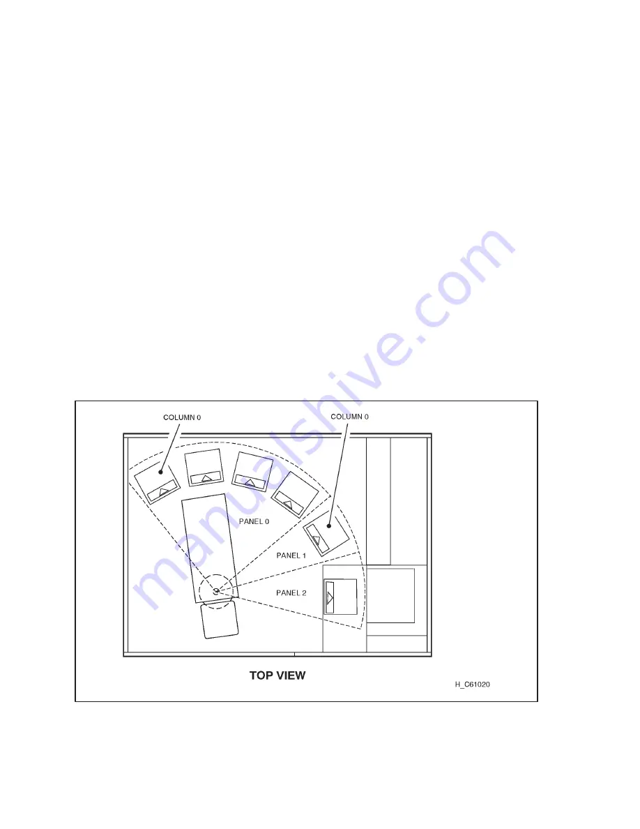
The LSM is configured by panel, column, row, and cell so that the LSM
management software can locate a cartridge. The LSM contains storage cells for
40, 60, 80, or 100 cartridges. Cartridges are stored in cell arrays that hold 6 or 14
cartridges, for a total of 20 cartridges per column. The columns are arranged in a
semicircle around the robot assembly. Figure 1–3 and Figure 1–4 show the cell
locations.
Note:
The cell located at the top of Panel 1, Column 1, is a designated cleaning
cartridge cell if you have the AUTO CLEAN feature enabled, as described
in section “AUTO CLEAN Feature” at the end of this chapter. If you do
not, you can use that cell for a data cartridge. You can use the View Config
section of Figure 2–4 in Chapter 2 to determine whether the feature is
enabled.
The array targets are used for robotic calibration during IPL.
The drive and CAP locations are not used to store cartridges.
The FREE THROW designation below the CAP is the location where the
hand can extend itself as an IPL test.
Figure 1–3.
Locating Cartridges—Top View
Summary of Contents for Surestore Tape Library Model 6/100
Page 1: ......
Page 2: ......
Page 3: ......
Page 6: ...Hardware Operator s Guide iv This page intentionally left blank ...
Page 10: ...Hardware Operator s Guide viii This page intentionally left blank ...
Page 14: ...Hardware Operator s Guide xii This page intentionally left blank ...
Page 18: ...Hardware Operator s Guide xvi ...
Page 20: ...Hardware Operator s Guide 1 2 Figure 1 1 LSM Major External Components ...
Page 26: ...Hardware Operator s Guide 1 8 This page intentionally left blank ...
Page 28: ...Hardware Operator s Guide 2 2 Figure 2 1 LSM Operator Panel Softkeys Indicators and Display ...
Page 31: ...Hardware Operator s Guide 2 5 Figure 2 3 Setting the SCSI Address ...
Page 36: ...Hardware Operator s Guide 3 2 Figure 3 1 DLT Handle Position ...
Page 41: ...Hardware Operator s Guide 3 7 Figure 3 3 Opening the LSM Front Door ...
Page 45: ...Hardware Operator s Guide 3 11 Figure 3 7 Locating Cartridges Panels Columns Rows Cells ...
Page 48: ...Hardware Operator s Guide 3 14 Figure 3 10 DLT Handle Position ...
Page 52: ...Hardware Operator s Guide 4 2 Figure 4 1 Inspecting a DLT Cartridge ...
Page 56: ...Hardware Operator s Guide 4 6 This page intentionally left blank ...
Page 64: ...Hardware Operator s Guide A 8 This page intentionally left blank ...
Page 67: ...X 3 Index ...
Page 68: ...Hardware Operator s Guide X 4 ...
Page 69: ...Hardware Operator s Guide X 5 ...
Page 70: ...Hardware Operator s Guide X 6 This page intentionally left blank ...
Page 72: ......
Page 73: ......
Page 74: ......


