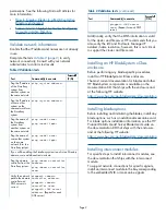
Figure 1 Interconnect bay numbering and device
mapping (c7000 enclosure)
Interconnect bay
label
Interconnect bay
Blade signal
1
NIC 1 (embedded)
2
NIC 2 (embedded)
3 and 4
Mezzanine 1
5 and 6
Mezzanine 2
7 and 8
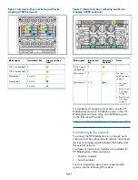
Figure 2 Interconnect bay numbering and device
mapping (c3000 enclosure)
Notes
Interconnect
bay label
Interconnect
bay
Blade signal
1
NICs 1 and 2
(embedded)
Four port
cards connect
to bay 2
2
Mezzanine 1
3, 4
Mezzanine 2
•
Four port
cards
•
Ports 1 and
3 connect
to bay 3
•
Ports 2 and
4 connect
to bay 4
For detailed port mapping information, see the HP
BladeSystem enclosure installation poster or the HP
BladeSystem enclosure setup and installation guide
on the following HP website:
http://www.hp.com/go/bladesystem/documentation
Connecting to the network
To connect the HP BladeSystem to a network, each
enclosure must be configured with network interconnect
devices to manage signals between the blades and
the external network.
Two types of interconnect modules are available for
HP BladeSystem c-Class enclosures:
•
Pass-thru modules
•
Switch modules
For more information about interconnect module
options, see the following HP website:
Page 3


