background image

A EVA4400 cabling diagrams

This appendix contains cabling diagrams for common EVA4400 installation environments. If you plan
to configure the EVA4400 with an iSCSI device, see the

HP StorageWorks EVA iSCSI connectivity

user guide

. See

Related documentation

for the location of this guide.

Connecting device port Fibre Channel cables to the EVA4400
(rear view)

This section shows two views of how you can connect cables to the controller.

Figure 22

shows the

controller mounted on top of the disk shelves in the rack, and

Figure 23

shows the controller with disk

shelves mounted above and below it.

1.

For configurations with the controller

above

the disk enclosures, attach the cables to the EVA as

shown in

Figure 22

.

NOTE:

All controller device port A cabling must be plugged into the A I/O modules on all enclosures.
All controller B device port cabling must be plugged into the B I/O modules on all enclosures.

HP StorageWorks 4400 Enterprise Virtual Array installation guide

81

Summary of Contents for StorageWorks 4400

Page 1: ...th America at 1 800 474 6836 Outside North America call HP technical support at the nearest location Telephone numbers for worldwide technical support are listed on the HP website http www hp com support To assist you in installing the EVA4400 videos of the procedures have been produced Go to the Services Media Library website http www hp com go sml and navigate to your product to view these video...

Page 2: ...t to change without notice The only warranties for HP products and services are set forth in the express warranty statements accompanying such products and services Nothing herein should be construed as constituting an additional warranty HP shall not be liable for technical or editorial errors or omissions contained herein WARRANTY STATEMENT To obtain a copy of the warranty for this product see t...

Page 3: ...ns 18 RAID levels 18 2 Prepare your site 21 Overview 21 Provide adequate structural support for the floor 21 Provide adequate clearance space and ventilation 21 Provide adequate and redundant sources of power 22 3 Remove product from packaging 23 Overview 23 4 Install components 25 Rack installation best practices 25 Attach the brackets for a longer chassis 26 Converting the rails 27 Attach the ra...

Page 4: ... Connecting through a public network 43 Connecting through a private network 44 Accessing HP Command View EVA on the management module 45 Changing the default operating mode 45 Accessing the WOCP through HP Command View EVA 46 8 Configuring management servers using HP SmartStart EVA Storage 47 Overview 47 9 Configuring application servers for Windows using HP SmartStart EVA Storage 49 Overview 49 ...

Page 5: ...driver stack 66 Configuring Emulex FCAs with the lpfc driver 67 Configuring QLogic FCAs with the qla2300 driver 68 Fabric setup and zoning 69 Sun StorEdge Traffic Manager MPxIO Sun Storage Multipathing 70 Configuring with Veritas Volume Manager 70 Configuring virtual disks from the host 72 Verifying virtual disks from the host 73 Labeling and partitioning the devices 73 VMware 74 Installing VMware...

Page 6: ...witch Management GUI 41 17 management module 44 18 WOCP Configure controller host ports page 46 19 Configure as management server choice 47 20 Configure storage initially or add storage later 49 21 Fibre Channel cabling for the EVA rear view top mounted controller 82 22 Fibre Channel cabling for the EVA rear view mid mounted controller 83 23 Cabling the controller to front end components Fibre Cha...

Page 7: ...HSV300 S controller enclosure in a direct connect configuration with array based management 86 29 HP StorageWorks 4400 Enterprise Virtual Array installation guide 7 ...

Page 8: ...1 Raid Level Comparison 19 2 Power cable connections 35 3 EVA4400 status lights during startup 38 4 EVA4400 status lights during operation 38 5 Operating system and host mode selection 53 6 Comparing console LUN to OS unit ID 63 7 8 ...

Page 9: ...management server running Windows for HP Command View EVA software server based management A management module running HP Command View EVA software array based management A CD ROM drive attached to either the management server or the server attached to the manage ment module Related documentation You can find the documents referenced in this guide on the Manuals page of the HP Business Support Cen...

Page 10: ...t emphasis Italic text File and directory names System output Code Commands their arguments and argument values Monospace text Code variables Command variables Monospace italic text Emphasized monospace text Monospace bold text WARNING Indicates that failure to follow directions could result in bodily harm or death CAUTION Indicates that failure to follow directions could result in damage to equip...

Page 11: ...e contacting HP collect the following information Product model names and numbers Technical support registration number if applicable Product serial numbers Error messages Operating system type and revision level Detailed questions Customer self repair HP customer self repair CSR programs allow you to repair your StorageWorks product If a CSR part needs replacing HP ships the part directly to you ...

Page 12: ...after removing the controller front bezel is shown in the circled area in Figure 1 Figure 1 Location of WWN and serial number NOTE For products ordered as bundled products that contain multiple products the product number and serial number needed for service and support is shown in the circled area in Figure 2 callouts 3 and 4 About this guide 12 ...

Page 13: ...sions firmware updates and other product resources HP websites For additional information see the following HP websites http www hp com http www hp com go storage http www hp com support manuals http www hp com support downloads Documentation feedback HP welcomes your feedback To make comments and suggestions about product documentation please send a message to storagedocsFeedback hp com All submi...

Page 14: ...tion checklist Figure 3 and Figure 4 illustrate the steps necessary to install the EVA hardware and HP Command View EVA software Each step is described in a subsequent chapter of this manual About this guide 14 ...

Page 15: ...Figure 3 Installation checklist HP StorageWorks 4400 Enterprise Virtual Array installation guide 15 ...

Page 16: ...Figure 4 Installation checklist cont d About this guide 16 ...

Page 17: ...ng the EVA HP recommends that you Develop an installation and configuration plan for your environment Review all videos and documentation Determine if the EVA will be fabric attached connected to Fibre Channel switch or direct attached connected to Fibre Channel adapter in server The EVA4400 is factory configured for fabric at tached To change to direct attached mode see Chapter 7 NOTE Models of t...

Page 18: ...Vraid is also referred to as redundancy in HP management software Virtual disks with HP Vraid use three key RAID methods data striping data mirroring and parity error checking Unlike traditional RAID all HP Vraid levels distribute data across all available physical disks Data striping improves speed by performing virtual disk I O with an entire group of physical disks at the same time Mirroring pr...

Page 19: ...ks provide as good or better performance than Vraid1 for applications that use sequential writes Vraid5 has much lower random write perform ance in comparison to Vraid1 but has much higher capacity ef ficiency Vraid5 provides a balance of data redundancy I O speed and efficient use of physical disk space Vraid5 uses about 20 more phys ical disk space than Vraid0 Vraid5 striping and double par ity ...

Page 20: ...Review and confirm your plans 20 ...

Page 21: ...3 hp com configurator Provide adequate structural support for the floor Calculate the total weight of your equipment and verify that your site can support the weight Provide adequate clearance space and ventilation Be sure to provide adequate clearance around the front and back of the racks Provide at least 25 inches 63 5 cm in the front of the rack to allow the doors to open fully and provide at ...

Page 22: ...ome from the same external power grid but occasionally may originate from different grids or even entirely different sources For protection against a power source failure obtain and include two uninterruptible power supplies in your installation For power consumption specifications see the QuickSpecs document at http www hp com go eva4400 Prepare your site 22 ...

Page 23: ...dules two fan modules and two battery modules installed Rack mounting hardware Two 2 0 meter FC copper cables Two power cords Installation documentation XCS controller software recovery CD Each FC disk shelf will contain One 2U M6412 disk enclosure two power supply modules two fan modules and two battery modules Rack mounting hardware kit Two 0 41 meter FC copper cables Two power cords 3 Inspect f...

Page 24: ...Remove product from packaging 24 ...

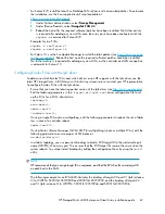
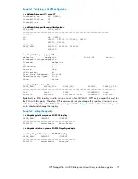
Page 25: ... or damage to the equipment be sure that At least two people lift the storage system during removal or installation if the weight exceeds 22 7 kg 50 lb If the system is being loaded into the rack above chest level a third person MUST assist with aligning the system with the rails while the other two people support the weight of the system The leveling jacks on the rack are extended to the floor Th...

Page 26: ...nto your cabinet such as for the controller enclosure you must remove the supplied shipping retaining bracket and install the smaller brackets supplied in the accessory kit NOTE A No 2 Phillips head screwdriver is required for this procedure 1 Remove the existing thumbscrew and shipping retaining bracket from the rear of the rail 2 Insert a screw through the bottom hole of the new bracket and loos...

Page 27: ... hole pins into the eight holes on the rails where the standard pins were removed Attach the rails NOTE The designation of left and right rail is made when looking at the front of the rack The rails are marked by an R right and L left stamped on the metal Consider the following when installing the rails Installing the rails does not require any tools for assembly HP recommends you install all the ...

Page 28: ... and slide the bracket to the farthest position on the rear of the rail This moves the bracket out of the way to allow you to install the chassis in the rails NOTE Figure 7 shows a drive enclosure rail and bracket If you are installing a longer chassis into your cabinet such as for a controller enclosure see Attach the brackets for a longer chassis for additional information Figure 7 Locking nut a...

Page 29: ...Align the enclosure with the rails and slide it into the rack Figure 9 Figure 9 Installing an enclosure view from front of rack 3 Continue sliding the enclosure into the rack until the front edge is flush with the front of the rack 1 Figure 10 4 Secure front of the enclosure to the front of the rack using the provided thumbscrews on the front of the device 2 Figure 10 and replace the front bezels ...

Page 30: ...to the drive bays Drives must be installed in the proper bay sequence in the enclosures for optimum HP Command View EVA performance and data integrity Example 1 If you have four enclosures and eight drives you should install four drives into bay 1 of each enclosure and four drives into bay 2 of each enclosure Do not install all the drives into enclosure 1 and leave the other enclosures empty CAUTI...

Page 31: ...osure Then to allow time for the internal disk to stop rotating wait approximately 10 seconds before completely removing the drive from the enclosure 1 As shown in Figure 12 unlatch the drive 1 swing out the handle 2 and slide the drive into the enclosure 3 2 Latch the handle when the drive is fully seated in the enclosure 15808 Figure 12 Installing drives into the enclosures Continue until you ha...

Page 32: ...ceiver modules on the FC ports Four SFPs are factory installed in the HSV300 S but you will need to install additional SFPs if you plan to use more than four switch ports If you purchased extra SFPs install them now NOTE The HSV300 S requires 4 Gb or higher SFPs Install components 32 ...

Page 33: ...ensure that the cabling in the back of the rack system does not interfere with system operation or maintenance Bind the cables loosely with cable ties and route the excess cables out of the way along the side of the rack When the cables are tied together and routed down the side of the rack system components and indicators are easily visible and accessible Attach a label near both ends of each cab...

Page 34: ... radius is 25 mm for 50 62 5 and 9 micron fiber optic cable Connecting device port Fibre Channel cables to the EVA rear view See Figure 22 and Figure 23 in Appendix A Connecting Fibre Channel cables to the EVA front end See Figure 24 and Figure 26 in Appendix A for front end connections with server based management See Figure 25 and Figure 27 in Appendix A for front end connections with array base...

Page 35: ...two separate power sources Protects you from downtime when one of the EVA power supplies fails Protects you from data loss when one or both of your power sources fails due to a pulled cable tripped breaker or local power outage The remaining power source or the UPS will power the EVA until power is restored to the source Depending on the cause and duration of the power outage you can use this time...

Page 36: ...Connect cables and power cords 36 ...

Page 37: ...osure is powered on the LED for the power standby buttons changes from amber to solid green Wait for a solid green LED on each disk enclosure to ensure each enclosure has successfully powered on 2 Apply power to each external Fibre Channel switch 3 Wait up to five minutes for the EVA to complete its startup routine and for the Fibre Channel switches to boot 4 Apply power to the servers in the SAN ...

Page 38: ...placeable units in the EVA Figure 14 EVA4400 front panel LEDs Table 4 EVA4400 status lights during startup Startup Condition LED Function Number Blinking blue UID Unit ID 1 Blinking green Enclosure external health 2 Blinking amber Enclosure fault warning 3 Solid amber Link to host 4 Solid amber Fan condition 5 2 LEDs Solid amber Battery condition 6 2 LEDs Table 5 EVA4400 status lights during opera...

Page 39: ... and hard drive LEDs and compare them with the patterns described in the documentation for these devices If the LEDs indicate a fault see the HP StorageWorks 4400 Enterprise Virtual Array user guide Figure 15 Rear and front view of the disk enclosure Verify the operating status of the Fibre Channel switches and adapters Verifying Fibre Channel switches To verify that your switches are operating pr...

Page 40: ...or complete switch configuration and management instructions see the HP StorageWorks Fabric OS 6 1 x administrator guide at http www hp com support manuals Under Storage click Disk Storage Systems and then click HP StorageWorks 4400 Enterprise Virtual Array under EVA Disk Arrays To configure an embedded switch in an HSV300 S controller 1 Obtain a laptop and an Ethernet cable straight through or cr...

Page 41: ...17 Figure 17 Switch Management GUI 4 Change the IP address and other settings of the switch as appropriate for your network You may also rename the switch or perform other configuration activities at this time 5 Remove the Ethernet cable from the first switch and connect the cable to the Ethernet port 2 Figure 16 of the other embedded switch Browse to http 10 77 77 78 for the Controller 2 switch a...

Page 42: ...ugh the EVA is not yet visible to the server verify that the server is operating properly A simple test is to verify that your operating system loaded and then open a software application or your browser If your server is not operating properly see the documentation that came with the server for help Turn on power 42 ...

Page 43: ...an MDI X port that supports straight through or crossover Ethernet cables Use a Cat 5e or greater cable to connect the management module from its Ethernet jack 1 Figure 18 to the management server Connecting to the management module You can connect to the management module through a public or a private network If you use a laptop to connect to the management module configure the laptop to have an ...

Page 44: ...itialized 9 Remove the LAN cable to the private network and reconnect the cable to the public network The new IP address is stored and remains in effect even when the storage system is shut down or restarted However the IP address will be lost if the storage system is uninitialized and the WOCP reset 10 From a computer on the public network browse to https newly configured ip ad dress 2373 and log...

Page 45: ...o access HP Command View EVA on the management module complete the following 1 Click Launch Command View EVA 2 Click Use management module server The logon window appears 3 Enter the security credentials for accessing HP Command View EVA Changing the default operating mode By default the EVA4400 is shipped to operate in a Fibre Channel switch environment and is configured in fabric mode If you cho...

Page 46: ...ler 7 Close the WOCP and remove the Ethernet cable from the server Accessing the WOCP through HP Command View EVA 1 Select the EVA4400 storage system to access 2 Select Hardware Controller Enclosure Management Module 3 Click Launch WOCP Rarely the Launch WOCP button may not appear due to invalid array state or if the management module IP address is unknow to HP Command View EVA Connecting to the m...

Page 47: ...ation for array based management see Completing the array configuration in the HP StorageWorks Command View EVA user guide Overview 1 Insert the HP SmartStart EVA Storage CD in the drive of the management server The HP SmartStart EVA Storage tool runs automatically 2 Read the conceptual information and browse online help 3 Click Configure as Management Server on the display 4 Follow the prompts to...

Page 48: ...Configuring management servers using HP SmartStart EVA Storage 48 ...

Page 49: ...rver as your management server The HP SmartStart EVA Storage tool runs automatically 2 Click and choose to configure either for the first time or to use additional storage 3 Repeat this configuration process for each server in your HP Command View EVA configuration Figure 21 Configure storage initially or add storage later HP StorageWorks 4400 Enterprise Virtual Array installation guide 49 ...

Page 50: ...Configuring application servers for Windows using HP SmartStart EVA Storage 50 ...

Page 51: ...ustering is connecting two or more computers together so that they behave like a single computer Clustering is used for parallel processing load balancing and fault tolerance See the HP StorageWorks Enterprise Virtual Array compatibility reference for the clustering software supported on each operating system Clustering is not supported on Linux Novell NetWare or VMware NOTE For OpenVMS you must m...

Page 52: ...tion See that documentation for complete instructions You need the following items to begin FCA boards and the manufacturer s installation instructions Server hardware manual for instructions on installing adapters Tools to service your server The FCA board plugs into a compatible I O slot PCI PCI X PCI E in the host system For instructions on plugging in boards see the hardware manual You can dow...

Page 53: ...Linux Linux Linux Mac OS X Unknown NetWare OVMS OpenVMS Sun Solaris Sun Solaris VMware VMware 4 Check the Host folder in the Navigation pane of HP Command View EVA to verify the host FCAs are added NOTE More information about HP Command View EVA is available at the following website http www hp com support manuals Click Storage Software under Storage and then select HP StorageWorks Command View EV...

Page 54: ...t correctly to the host you selected Verify the FCA switch settings Verify that the virtual disk is presented to the host Verify zoning Configuring virtual disks from the host After you create the virtual disks on the EVA4400 and rescan or restart the host follow the host specific conventions for configuring these new disk resources For instructions see the documentation included with your server ...

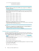
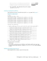
Page 55: ...5 sdisk CLAIMED DEVICE HP HSV300 dev dsk c10t0d5 dev rdsk c10t0d5 disk 50 0 6 0 0 39 28 0 0 0 6 sdisk CLAIMED DEVICE HP HSV300 dev dsk c10t0d dev rdsk c10t0d6 disk 51 0 6 0 0 39 28 0 0 0 7 sdisk CLAIMED DEVICE HP HSV300 dev dsk c10t0d7 dev rdsk c10t0d7 Creating volume groups on a virtual disk using vgcreate You can create a volume group on a virtual disk by issuing a vgcreate command This builds t...

Page 56: ...age product Adding hosts To determine the active FCAs on the IBM AIX host enter lsdev Cc adapter grep fcs Output similar to the following appears fcs0 Available 1H 08 FC Adapter fcs1 Available 1V 08 FC Adapter lscfg vl fcs0 fcs0 U0 1 P1 I5 Q1 FC Adapter Part Number 80P4543 EC Level A Serial Number 1F4280A419 Manufacturer 001F Feature Code Marketing ID 280B FRU Number 80P4544 Device Specific ZM 3 N...

Page 57: ...ble driver failover mode scenarios include If an hp_qla2x00src driver RPM is already installed then the new driver RPM uses the failover of the previous driver package If there is no QLogic driver module qla2xxx module loaded the driver defaults to failover mode This is also true if an inbox driver is loaded that does not list output in the proc scsi qla2xxx directory If there is a driver loaded i...

Page 58: ... hp src hp_qla2x00src unload sh modprobe qla2xxx_conf modprobe qla2xxx modprobe qla2300 modprobe qla2400 The command to reboot the server is reboot CAUTION If the boot device is attached to the SAN you must reboot the host To verify which RPM versions are installed use the rpm command with the q option For example rpm q hp_qla2x00src rpm q fibreutils Upgrading Linux components If you have any inst...

Page 59: ...on portion of the RPM contains code to check for non HP storage The reason for doing this is so that the RPM does not overwrite any settings that another vendor may be using You can skip the detection by setting the environmental variable HPQLAX00FORCE to y by issuing the following commands HPQLA2X00FORCE y export HPQLA2X00FORCE You can also use the F option of the INSTALL script by entering the f...

Page 60: ... source RPM for 2 4 kernel based distributions and the 8 xx version of the hp_qla2x00 source RPM for 2 6 kernel based distributions Use the following procedure to create the binary RPM from the source RPM 1 Select one of the following options Enter the INSTALL S command NOTE If you execute the INSTALL S command you do not have to complete step 2 through step 4 Install the source RPM by issuing the...

Page 61: ...wnloaded from the following website http h20000 www2 hp com bizsupport You can load the QL2x00 HAM driver with optional switches to modify driver functionality Command examples for both single path and multiple path are Single Path Load QL2x00 HAM Slot 2 Luns allpaths Portnames startunit Multiple Path Load QL2x00 Ham Slot 2 luns allpaths portnames Installing Novell NetWare drivers NOTE The QL2x00 ...

Page 62: ... on SP6 with CPQSHD CDM Using the CFG NLM utility You can use the CFG NLM utility to determine WWN numbers To use the CFG NLM utility 1 Copy the CFG NLM utility from the C nwserver drivers unsupdrv to the system directory of the server 2 From the console enter the cfg I command 3 Go to the Logger screen and copy the WWN numbers that are displayed 4 Ensure that the host FCAs have been added by insp...

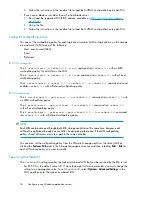
Page 63: ...767 ensuring that the number you enter is unique within the SAN An OS Unit ID greater than 9999 is not capable of being MSCP served CAUTION It is possible to enter a duplicate Console LUN ID or OS unit ID number You must ensure that you enter a Console LUN ID and OS Unit ID that is not already in use A duplicate Console LUN ID or OS Unit ID can allow the OpenVMS host to corrupt data through confus...

Page 64: ... the WWN for that particular port Output similar to the following appears Adapter Path Acpi PNP0002 0300 Pci 01 01 Adapter WWPN 50060B00003B478A Adapter WWNN 50060B00003B478B Adapter S N 3B478A Scanning the bus Enter the following command to scan the bus for the OpenVMS virtual disk MC SYSMAN IO AUTO LOG A listing of LUNs detected by the scan process is displayed Verify that the new LUNs appear NO...

Page 65: ...ted 704 Path PGB0 5000 1FE1 0027 0A3D BRCK18 Error count 0 Operations completed 853 Path PGB0 5000 1FE1 0027 0A3F BRCK18 current path Error count 2 Operations completed 826 Path MSCP VMS24 Error count 0 Operations completed 0 You can also use the SHOW DEVICE DG command to display a list of all Fibre Channel disks presented to the OpenVMS host NOTE Restarting the host system shows any newly present...

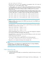
Page 66: ...ich path each virtual disk uses You can use the SHOW DEV FULL command to display the path identifiers For additional information on using OpenVMS commands see the OpenVMS help file HELP TOPIC For example the following command displays help information for the MOUNT command HELP MOUNT Sun Solaris Loading the operating system and software Follow the manufacturer s instructions for loading the operat...

Page 67: ...Emulex FCAs with the lpfc driver Ensure that you have the latest supported version of the lpfc driver see http www emulex com Edit the following parameters in the kernel drv lpfc conf driver configuration file to set up the FCAs for a SAN infrastructure topology 2 scan down 0 nodev tmo 60 linkdown tmo 60 If using a single FCA and no multipathing edit the following parameter to reduce the risk of d...

Page 68: ...very after configuring the file NOTE The lpfc driver is not supported for Sun StorEdge Traffic Manager Sun Storage Multipathing To configure an Emulex FCA using the Sun SAN driver stack see Configuring the FCAs with the Sun SAN driver stack on page 66 Configuring QLogic FCAs with the qla2300 driver See the latest HP StorageWorks 4400 Enterprise Virtual Array release notes or contact your HP repres...

Page 69: ...p to eight targets If the qla2300 driver is version 4 13 01 or earlier for each LUN that users will access add an entry to the kernel drv sd conf file name sd class scsi target 20 lun 1 name sd class scsi target 21 lun 1 name sd class scsi target 30 lun 1 name sd class scsi target 31 lun 1 If LUNs are preconfigured in the kernel drv sd conf file after changing the configuration file use the devfsa...

Page 70: ...ays are certified for VxVM support When you install FCAs ensure that the driver parameters are set correctly Failure to do so can result in a loss of path failover in DMP For information about setting FCA parameters see Configuring the FCAs with the Sun SAN driver stack on page 66 and the FCA manufacturer s instructions The DMP feature requires an Array Support Library ASL and an Array Policy Modu...

Page 71: ...ure all ENCLR_NAME ENCLR_TYPE ENCLR_SNO STATUS ARRAY_TYPE Disk Disk DISKS CONNECTED Disk EVA80000 EVA8000 50001FE1002709E0 CONNECTED A A A HP By default the EVA iopolicy is set to Round Robin For VxVM 4 1 MP1 only one path is used for the I Os with this policy Therefore HP recommends that you change the iopolicy to Adaptive in order to use all paths to the LUN on the primary controller Example 2 s...

Page 72: ...ve the WWLUN ID as part of the format e scsi inquiry output however it is cumbersome and hard to read For example 09 e8 20 04 00 00 00 00 00 00 35 30 30 30 31 46 50001F 45 31 30 30 32 37 30 39 45 30 35 30 30 30 31 46 E1002709E050001F 45 31 30 30 32 37 30 39 45 38 36 30 30 35 30 38 E1002709E8600508 42 34 30 30 31 30 33 30 45 34 30 30 30 30 35 30 B4001030E4000050 30 30 30 30 42 32 30 30 30 30 00 00 ...

Page 73: ...GC qla 4 fp 0 0 ssd w50001fe1002709f8 1 2 c2t50001FE1002709F8d2 HP HSV210 5100 cyl 126 alt 2 hd 128 sec 128 pci 1f 4000 QLGC qla 4 fp 0 0 ssd w50001fe1002709f8 2 3 c2t50001FE1002709FCd1 HP HSV210 5100 cyl 126 alt 2 hd 128 sec 128 pci 1f 4000 QLGC qla 4 fp 0 0 ssd w50001fe1002709fc 1 4 c2t50001FE1002709FCd2 HP HSV210 5100 cyl 126 alt 2 hd 128 sec 128 pci 1f 4000 QLGC qla 4 fp 0 0 ssd w50001fe100270...

Page 74: ...try of the presented volume varies with size always select autoconfigure as the disk type 6 if you are not using Veritas Volume Manager use the partition command to create or adjust the partitions 7 Repeat this labeling procedure for each new device Use the disk command to select another disk 8 When you finish labeling the disks enter quit or press Ctrl D to exit the format utility For more inform...

Page 75: ... root wwpn pl nl vmhba0 210000e08b09402b QLogic 6 1 0 nl vmhba1 210000e08b0ace2d QLogic 6 2 0 nl root gnome7 root Check the proc scsi qla2300 X directory where X is a bus instance number Look for the SCSI device information section Output similar to the following is displayed SCSI Device Information scsi qla0 adapter node 200000e08b0b0638 scsi qla0 adapter port 210000e08b0b0638 Configuring the ESX...

Page 76: ...n vmhba0 0 1 command sets vmhba0 0 1 with an MRU multipathing policy The esxcfg mpath policy fixed lun vmhba0 0 1 command sets vmhba1 0 1 with a Fixed multipathing policy The esxcfg mpath preferred path vmhba2 0 1 lun vmhba2 0 1 command sets vmhba2 0 1 with a Preferred multipathing policy NOTE Each LUN can be accessed through both EVA storage controllers at the same time however each LUN path is o...

Page 77: ...r are not listed check the cable connections and perform a rescan on the appropriate FCA For example For ESX 2 5 x enter the cos rescan sh vmhba0 command For ESX 3 x enter the esxcfg rescan vmhba0 command If paths or LUNs remain missing see the VMware or HP StorageWorks documentation for troubleshooting information Verifying virtual disks from the host To verify that the host can access the virtua...

Page 78: ...Configuring non Windows application servers 78 ...

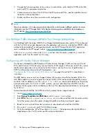
Page 79: ...rt Software HP recommends you install HP s Insight Remote Support software part number RSSWMBASE from www software hp com to complete this installation HP Insight Remote Support helps you reduce costs save time and ensure maximum system availability by providing remote monitoring intelligent event diagnosis and the automatic secure submission of hardware event notifications This technology has bee...

Page 80: ...nowledgement and status returns Remote Support Pack contains event monitoring and proactive service support including assessments and analysis for nearly all HP servers storage networks and SAN environments plus selected Dell and IBM Windows servers that have a support obligation with HP including proactive service contracts The HP contract and warranty entitlement feature of HP SIM requires this ...

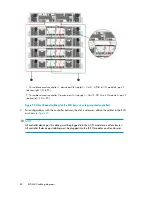
Page 81: ...of how you can connect cables to the controller Figure 22 shows the controller mounted on top of the disk shelves in the rack and Figure 23 shows the controller with disk shelves mounted above and below it 1 For configurations with the controller above the disk enclosures attach the cables to the EVA as shown in Figure 22 NOTE All controller device port A cabling must be plugged into the A I O mod...

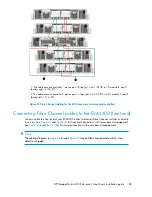
Page 82: ...I O A P2 Figure 22 Fibre Channel cabling for the EVA rear view top mounted controller 2 For configurations with the controller between the disk enclosures attach the cables to the EVA as shown in Figure 23 NOTE All controller device port A cabling must be plugged into the A I O modules on all enclosures All controller B device port cabling must be plugged into the B I O modules on all enclosures E...

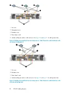
Page 83: ...onnecting Fibre Channel cables to the EVA4400 front end You can cable the front end of your EVA4400 either to external Fibre Channel switches or directly to servers See Figure 24 and Figure 26 for front end connections with server based management See Figure 25 and Figure 27 for front end connections with array based management NOTE The cabling diagrams in Figure 24 through Figure 27 require fabri...

Page 84: ...ntroller to front end components Fibre Channel to switch detail view with server based management 1 File server 2 Database server 3 Fiber channel switch 4 Indicates cabling connections to disk enclosures See Figure 22 and Figure 23 for cabling connections Figure 25 Cabling the controller to front end components Fibre Channel to switch detail view with array based management EVA4400 cabling diagram...

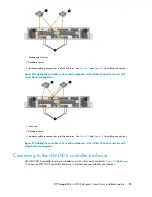
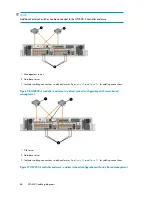
Page 85: ... cabling connections to disk enclosures See Figure 22 and Figure 23 for cabling connections Figure 27 Cabling the controller to front end components direct Fibre Channel to servers with array based management Connecting to the HSV300 S controller enclosure The HSV 300 S controller enclosure includes a switch within each controller Figure 28 and Figure 29 shows an HSV300 S controller enclosure in a...

Page 86: ...gure 23 for cabling connections Figure 28 HSV300 S controller enclosure in a direct connect configuration with server based management 1 File server 2 Database server 3 Indicates cabling connections to disk enclosures See Figure 22 and Figure 23 for cabling connections Figure 29 HSV300 S controller enclosure in a direct connect configuration with array based management EVA4400 cabling diagrams 86 ...

Reviews: