background image

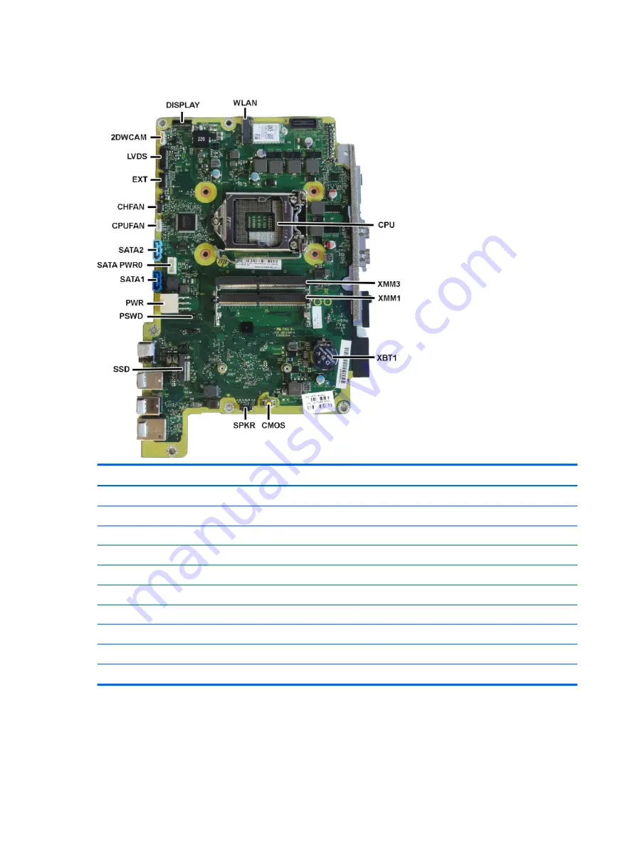
System board callouts

Sys Bd Label

Color

Component


Sys Bd Label

Color

Component

DISPLAY

Black

Display connector


PWR

White

Main power

WLAN

Black

WLAN module


SATA1

Dark blue

Second hard drive

CPU

Black

Processor socket


SATAPWR0

White

Hard drive power

XMM3

Black

Memory module


SATA2

Light blue

Hard drive

XMM1

Black

Memory module


CPUFAN

White

Fan connector

XBT1

Black

RTC battery


CHFAN

Black

Fan connector

CMOS

Yellow

Reset CMOS


EXT

Black

PS2/serial board

SPKR

Black

Speaker


LVDS

Black

Display connector

SSD

Black

M.2 SSD drive


2DWCAM

White

Webcam connector

PSWD

Green

Clear system passwords


42

Chapter 4   Removal and Replacement Procedures

Summary of Contents for ProOne 600 G3

Page 1: ...Maintenance Service Guide HP ProOne 600 G3 21 inch All in One Business PC ...

Page 2: ... July 2017 Document Part Number 913339 001 Product notice This user guide describes features that are common to most models Some features may not be available on your computer Not all features are available in all editions of Windows This computer may require upgraded and or separately purchased hardware drivers and or software to take full advantage of Windows functionality Go to http www microso...

Page 3: ...ollow directions could result in bodily harm or loss of life CAUTION Text set off in this manner indicates that failure to follow directions could result in damage to equipment or loss of information NOTE Text set off in this manner provides important supplemental information iii ...

Page 4: ...iv About This Book ...

Page 5: ... 11 Generating static 12 Preventing electrostatic damage to equipment 12 Personal grounding methods and equipment 13 Grounding the work area 13 Recommended materials and equipment 13 Operating guidelines 14 Routine care 14 General cleaning safety precautions 14 Cleaning the Computer Case 15 Cleaning the keyboard 15 Cleaning the display 15 Cleaning the mouse 16 Service considerations 16 Tools and s...

Page 6: ...cess panel 24 Locating internal components 25 Drives 26 Replacing a hard disc drive 26 Removing a 2 5 inch hard disc drive 26 Installing a 2 5 inch hard disc drive 28 Replacing the optical drive 29 System board EMI shield 30 Memory 31 Battery 33 WLAN module 34 Heat sink 35 Processor 36 Serial PS2 board 38 System board 39 System board callouts 42 VESA mounting bracket 43 Power supply 44 Fan assembl...

Page 7: ...audio problems 82 Solving printer problems 83 Solving keyboard and mouse problems 84 Solving hardware installation problems 85 Solving network problems 86 Solving memory problems 88 Solving USB flash drive problems 90 Solving Internet access problems 91 Solving software problems 92 8 Backing up restoring and recovering 93 Creating recovery media and backups 93 Creating HP Recovery media select pro...

Page 8: ...nd resetting CMOS 105 Resetting the password jumper 105 Clearing and resetting the BIOS 107 Appendix A Power cord set requirements 108 General requirements 108 Japanese power cord requirements 108 Country specific requirements 109 Appendix B Statement of memory volatility 110 Nonvolatile memory usage 112 Questions and answers 114 Using HP Sure Start select models only 115 Appendix C Specifications...

Page 9: ...horizontal operation of the AiO is not supported and may lead to thermal issues NOTE For the latest specifications or additional specifications on this product go to http www hp com go quickspecs and search for your specific display model to find the model specific QuickSpecs Overview 1 ...

Page 10: ...Front components Component Component 1 Webcam LED 4 Webcam microphone 2 Webcam shutter select models only 5 Speakers select models only 3 Webcam lens 2 Chapter 1 Product features ...

Page 11: ...components Component Component 1 Power button 5 HP SD media card reader 2 USB Type A charging ports 6 Optical disc drive 3 USB Type A ports 7 Optical disc drive eject button 4 Headset jack Side components 3 ...

Page 12: ...t Component 1 Security cable slot 6 DisplayPort port 2 Serial port 7 USB Type A ports 2 3 PS 2 keyboard connector 8 USB Type A ports 2 4 PS 2 mouse connector 9 RJ 45 network jack 5 Power connector 4 Chapter 1 Product features ...

Page 13: ...forms preinstalled with Windows 8 or Windows 8 1 do not have the physical label but have a Digital Product Key electronically installed NOTE This Digital Product Key is automatically recognized and activated by Microsoft Operating Systems on a reinstall of the Windows 8 or Windows 8 1 operating system with HP approved recovery methods 2 Service label Provides important information to identify your...

Page 14: ...tinually improves and changes product parts For complete and current information on supported parts for your computer go to http partsurfer hp com select your country or region and then follow the on screen instructions System parts 6 Chapter 2 Illustrated parts catalog ...

Page 15: ...el 16 System board 17 Power supply 160 W 18 Fan WLAN modules Intel Dual Band Wireless AC 7265 NV Intel Dual Band Wireless AC 8265 vPro Intel Dual Band Wireless AC 8265 non vPro Intel Dual Band Wireless AC 3168 802 11bgn 1x1 single band Bluetooth 4 1 combo module Optical drive bezel blank for use in models without an optical drive Optical drive bezel Mylar cover for use in models without speakers C...

Page 16: ...FIPS Solid state drive not illustrated 1 TB solid state drive TLC 512 GB solid state drive PCIe SS TLC 512 GB solid state drive PCIe DS 512 GB solid state drive SATA 3 OPAL 2 0 self encrypting SED TLC 512 GB solid state drive SATA 3 FIPS TLC 256 GB solid state drive PCIe 256 GB solid state drive PCIe TLC 256 GB solid state drive SATA 3 TLC 256 GB solid state drive FIPS TLC 256 GB solid state drive...

Page 17: ... GHz Intel Core i7 6700 3 4 GHz Intel Core i5 6600 3 3 GHz Intel Core i5 6500 3 2 GHz Intel Core i3 6100 3 7 GHz Intel Pentium G4620 3 7 GHz Intel Pentium G4600 3 6 GHz Intel Pentium G4560 3 5 GHz Intel Pentium G4400 3 3 GHz Intel Celeron G3950 3 0 GHz Intel Celeron G3930 2 9 GHz Intel Celeron G3900 2 8 GHz Cables Description Backlight cable BOE LGD AUO Serial port cable Hard drive optical drive S...

Page 18: ...1 4 Adapter USB to serial port Keyboards and mice Description Keyboard USB USB slim USB Washable USB Essential Conferencing Wireless with mouse Smartcard PS 2 slim Healthcare Antimicrobial Mouse Gray Antimicrobial USB PS2 Washable Hardened USB optical PS 2 optical USB laser 10 Chapter 2 Illustrated parts catalog ...

Page 19: ...arge information A sudden discharge of static electricity from your finger or other conductor can destroy static sensitive devices or microcircuitry Often the spark is neither felt nor heard but damage occurs An electronic device exposed to electrostatic discharge ESD may not appear to be affected at all and can work perfectly throughout a normal cycle The device may function normally for a while ...

Page 20: ...ng electrostatic damage to equipment Many electronic components are sensitive to ESD Circuitry design and structure determine the degree of sensitivity The following packaging and grounding precautions are necessary to prevent damage to electric components and accessories To avoid hand contact transport products in static safe containers such as tubes bags or boxes Protect all electrostatic parts ...

Page 21: ... work surface and properly grounded tools and equipment Use static dissipative mats foot straps or air ionizers to give added protection Handle electrostatic sensitive components parts and assemblies by the case or PCB laminate Handle them only at static free work areas Turn off power and input signals before inserting and removing connectors or test equipment Use fixtures made of static safe mate...

Page 22: ... cover or side panel removed Do not stack computers on top of each other or place computers so near each other that they are subject to each other s re circulated or preheated air If the computer is to be operated within a separate enclosure intake and exhaust ventilation must be provided on the enclosure and the same operating guidelines listed above will still apply Keep liquids away from the co...

Page 23: ...se safety glasses equipped with side shields before attempting to clean debris from under the keys Visible debris underneath or between the keys may be removed by vacuuming or shaking Canned pressurized air may be used to clean debris from under the keys Caution should be used as too much air pressure can dislodge lubricants applied under the wide keys If you remove a key use a specially designed ...

Page 24: ... the unit HP strongly recommends that all screws removed during disassembly be kept with the part that was removed then returned to their proper locations CAUTION Metric screws have a black finish U S screws have a silver finish and are used on hard drives only CAUTION As each subassembly is removed from the computer it should be placed away from the work area to prevent damage Cables and connecto...

Page 25: ... hard drive to liquids temperature extremes or products that have magnetic fields such as displays or speakers Lithium coin cell battery The battery that comes with the computer provides power to the real time clock and has a minimum lifetime of about three years See the appropriate removal and replacement chapter for the chassis you are working on in this guide for instructions on the replacement...

Page 26: ...op of expansion cards or memory modules Printed circuit cards like these are not designed to take excessive pressure on them Keep cables clear of sliding or moveable parts to prevent them from being cut or crimped when the parts are moved When folding a flat ribbon cable never fold to a sharp crease Sharp creases may damage the wires Some flat ribbon cables come prefolded Never change the folds on...

Page 27: ...own the computer 3 After the system has completely shut down disconnect the power adapter from the back of the computer 4 If a cable lock is installed on the rear of the unit remove the lock 5 Disconnect all other attached cables from the back of the computer 6 Place the computer face down on a soft flat surface HP recommends that you set down a blanket towel or other soft cloth to protect the scr...

Page 28: ...1 3 Rotate the stand down until it clicks into place 2 Removing an easel stand To remove the stand 1 Remove all removable media such as optical discs or USB flash drives from the computer 2 Turn off the computer properly through the operating system then turn off any external devices 3 Disconnect the AC power cord from the AC outlet and disconnect any external devices 4 Place the computer face dow...

Page 29: ...ce the computer face down on a soft flat surface HP recommends that you set down a blanket towel or other soft cloth to protect the bezel and screen surface from scratches or other damage 2 Engage the hooks in the top of the stand in the two large holes in the upper part of the back of the computer 1 3 Rotate the stand down until it clicks into place 2 Attaching and removing a stand 21 ...

Page 30: ...t and disconnect any external devices 4 Place the computer face down on a soft flat surface HP recommends that you set down a blanket towel or other soft cloth to protect the bezel and screen surface from scratches or other damage 5 Remove the rear port cover if it is installed For instructions see Rear port cover on page 23 6 Press the release latch under the stand 1 7 Lift the stand up 2 and the...

Page 31: ...and see Attaching and removing a stand on page 20 3 If the security lock screw is secured unscrew it with a T15 tamper resistant Torx security screwdriver 4 Slide the rear port cover retainer tabs toward each other 1 to release the port cover 5 Pull the port cover 2 toward the bottom and off the computer Rear port cover 23 ...

Page 32: ...assemble the computer on page 19 2 Remove the rear port cover see Rear port cover on page 23 3 Remove the stand see Attaching and removing a stand on page 20 4 Pull up at the two recessed areas on at bottom of the access panel and then lift the access panel off the computer 5 Lift the access panel off the computer To replace the access panel reverse the removal procedures 24 Chapter 4 Removal and ...

Page 33: ...Locating internal components Component Component 1 Optical disc drive 3 Battery 2 Hard drive 4 Memory modules Locating internal components 25 ...

Page 34: ... TLC 256 GB solid state drive OPAL 2 0 self encrypting SED TLC Replacing a hard disc drive The 2 5 inch primary hard drive is installed on the left side of the computer on top of the optical disc drive ODD To locate the hard drive on the system board see Locating internal components on page 25 Removing a 2 5 inch hard disc drive 1 Prepare the computer for disassembly see Preparing to disassemble t...

Page 35: ... the four mounting screws from the 2 5 inch hard drive Be sure to keep the screws together with the blue rubber grommets to use to install a replacement drive For instructions on installing a hard disc drive see Installing a 2 5 inch hard disc drive on page 28 Drives 27 ...

Page 36: ...acing the power and data cables 3 Connect the power and data cables to the hard drive 1 4 Place the hard drive into the drive cage and slide it firmly away from the edge of the computer 2 until the hard drive snaps into place Be sure that the hard drive latch has moved back into place to cover the grommet on the side of the hard drive 28 Chapter 4 Removal and Replacement Procedures ...

Page 37: ... access panel see Access panel on page 24 5 Remove the hard drive see Removing a 2 5 inch hard disc drive on page 26 6 Push and hold the green tab 1 while pushing in the green latch 2 at the back of the optical disc drive enclosure and slide the drive out of the chassis 3 7 Pull the green latch off the optical disc drive Keep this latch to install on the new optical disc drive 8 Align the three pi...

Page 38: ...s secure the shield To remove the system board shield 1 Prepare the computer for disassembly see Preparing to disassemble the computer on page 19 2 Remove the rear port cover see Rear port cover on page 23 3 Remove the stand see Attaching and removing a stand on page 20 4 Remove the access panel see Access panel on page 24 5 Lift the electromagnetic interference EMI shield off the system board To ...

Page 39: ...logies single sided and double sided SODIMMs Note The system will not operate properly if you install unsupported SODIMM memory SODIMMs constructed with x8 and x16 DDR devices are supported memory modules constructed with x4 SDRAM are not supported The system will automatically operate in single channel mode dual channel mode or flex mode depending on how the memory modules are installed Refer to ...

Page 40: ...sassemble the computer on page 19 2 Remove the rear port cover see Rear port cover on page 23 3 Remove the stand see Attaching and removing a stand on page 20 4 Remove the access panel see Access panel on page 24 5 Remove the system board shield see System board EMI shield on page 30 6 To remove a memory module press outward on the two latches on each side of the SODIMM 1 then pull the SODIMM out ...

Page 41: ...ore beginning these procedures ensure that you are discharged of static electricity by briefly touching a grounded metal object NOTE The lifetime of the lithium battery can be extended by plugging the computer into a live AC wall socket The lithium battery is only used when the computer is NOT connected to AC power HP encourages customers to recycle used electronic hardware HP original print cartr...

Page 42: ...e Rear port cover on page 23 3 Remove the stand see Attaching and removing a stand on page 20 4 Remove the access panel see Access panel on page 24 5 Remove the system board shield see System board EMI shield on page 30 6 Disconnect the antenna cables from the module 1 7 Remove the Phillips screw 2 that secures the module to the computer 8 Lift the module to a 45 degree angle and then pull it away...

Page 43: ...he non captive Torx screw from the top end of the heat sink 1 7 In the order indicated on the heat sink loosen the silver captive Torx screws 2 CAUTION Remove heat sink retaining screws in diagonally opposite pairs as in an X to even the downward forces on the processor This is especially important as the pins on the socket are very fragile and any damage to them may require replacing the system b...

Page 44: ... Intel Celeron G3950 3 0 GHz Intel Celeron G3930 2 9 GHz Intel Celeron G3900 2 8 GHz 1 Prepare the computer for disassembly see Preparing to disassemble the computer on page 19 2 Remove the rear port cover see Rear port cover on page 23 3 Remove the stand see Attaching and removing a stand on page 20 4 Remove the access panel see Access panel on page 24 5 Remove the system board shield see System ...

Page 45: ...le damage Once pins are damaged it may be necessary to replace the system board The heat sink must be installed within 24 hours of installing the processor to prevent damage to the processor s solder connections NOTE After installing a new processor onto the system board always update the system ROM to ensure that the latest version of the BIOS is being used on the computer The latest system BIOS ...

Page 46: ...ear port cover see Rear port cover on page 23 3 Remove the stand see Attaching and removing a stand on page 20 4 Remove the access panel see Access panel on page 24 5 Disconnect the cable 1 from the board 6 Remove the two Torx screws 2 that secure the board and then rotate the board up and remove it from the computer 3 7 Remove the serial PS2 board from the computer To install the serial PS2 board...

Page 47: ...ve the stand see Attaching and removing a stand on page 20 4 Remove the access panel see Access panel on page 24 5 Remove the system board shield see System board EMI shield on page 30 6 Remove the memory modules see Memory on page 31 7 Remove the WLAN module see WLAN module on page 34 8 Remove the heat sink see Heat sink on page 35 9 Remove the processor see Processor on page 36 10 Disconnect all...

Page 48: ...e SMBIOS information in Computer Setup 1 Turn on or restart the computer 2 Press Esc while the Press the ESC key for Startup Menu message is displayed at the bottom of the screen NOTE If you do not press Esc at the appropriate time you must restart the computer and again press Esc when the display light turns green to access the utility 3 Press F10 to enter Computer Setup 4 Go to Main Set Machine ...

Page 49: ... Byte string The feature byte string is case sensitive The label includes spaces after every four characters You can enter or ignore these spaces their only purpose is to help with data entry There is a character limitation of 40 bytes per line When you reach this limit go to the next line to continue data entry BIOS ignores the spaces and lines If you make an error during data entry the data will...

Page 50: ...SATAPWR0 White Hard drive power XMM3 Black Memory module SATA2 Light blue Hard drive XMM1 Black Memory module CPUFAN White Fan connector XBT1 Black RTC battery CHFAN Black Fan connector CMOS Yellow Reset CMOS EXT Black PS2 serial board SPKR Black Speaker LVDS Black Display connector SSD Black M 2 SSD drive 2DWCAM White Webcam connector PSWD Green Clear system passwords 42 Chapter 4 Removal and Rep...

Page 51: ...age 23 3 Remove the stand see Attaching and removing a stand on page 20 4 Remove the access panel see Access panel on page 24 5 Remove the system board shield see System board EMI shield on page 30 6 Remove the cable that is routing along the top and left side of the mounting bracket 1 7 Remove the five Torx screws 2 and then remove the bracket from the computer To replace the VESA mounting bracke...

Page 52: ...e Rear port cover on page 23 3 Remove the stand see Attaching and removing a stand on page 20 4 Remove the access panel see Access panel on page 24 5 Remove the VESA mounting bracket see VESA mounting bracket on page 43 6 Disconnect the cable from the system board 1 7 Lift the power supply out the computer 2 To replace the VESA mounting bracket reverse the removal procedures 44 Chapter 4 Removal a...

Page 53: ... the stand see Attaching and removing a stand on page 20 4 Remove the access panel see Access panel on page 24 5 Remove the system board shield see System board EMI shield on page 30 6 Remove the VESA mounting bracket see VESA mounting bracket on page 43 7 Disconnect the two fan cables from the system board 1 8 Remove the four Torx screws that secure the fan assembly to the computer 2 9 Remove the...

Page 54: ... page 23 3 Remove the stand see Attaching and removing a stand on page 20 4 Remove the access panel see Access panel on page 24 5 Remove the system board shield see System board EMI shield on page 30 6 Remove the VESA bracket see VESA mounting bracket on page 43 7 Remove the two screws 1 that secure the optical drive connector to the computer 8 Disconnect the cables from the system board connector...

Page 55: ... 19 2 Remove the rear port cover see Rear port cover on page 23 3 Remove the stand see Attaching and removing a stand on page 20 4 Remove the access panel see Access panel on page 24 5 Remove the five Torx screws 1 that secure the trim to the computer 6 Rotate the bottom of the trim up and off the computer 2 To install the top trim reverse the removal procedures Top trim 47 ...

Page 56: ...ble the computer on page 19 2 Remove the rear port cover see Rear port cover on page 23 3 Remove the stand see Attaching and removing a stand on page 20 4 Remove the access panel see Access panel on page 24 5 Remove the top trim see Top trim on page 47 6 Remove the two Torx screws 1 that secure the webcam module bracket to the computer 7 Disconnect the cable from the webcam module 2 8 Remove the w...

Page 57: ...hing and removing a stand on page 20 4 Remove the access panel see Access panel on page 24 5 Remove the system board shield see System board EMI shield on page 30 6 Remove the top trim see Top trim on page 47 7 Disconnect the antennas from the WLAN module 1 8 Peel the transceivers off the frame 2 9 Remove the cables from the clips along the routing path 3 To install the antenna reverse the removal...

Page 58: ...ng a stand on page 20 4 Remove the access panel see Access panel on page 24 5 Remove the system board shield see System board EMI shield on page 30 6 Remove the top trim see Top trim on page 47 7 Remove the four Torx screws 1 that secure the right trim to the computer and then rotate the trim away from the computer to remove 2 To install the right trim reverse the removal procedures 50 Chapter 4 R...

Page 59: ...stand see Attaching and removing a stand on page 20 4 Remove the access panel see Access panel on page 24 5 Remove the top trim see Top trim on page 47 6 Remove the optical drive see Replacing the optical drive on page 29 7 Remove the six Torx screws 1 that secure the left trim to the computer 8 Rotate the trim off the computer 2 To install the left trim reverse the removal procedures Left trim 51...

Page 60: ...ving a stand on page 20 4 Remove the access panel see Access panel on page 24 5 Remove the serial PS2 board see Serial PS2 board on page 38 6 Remove the top trim see Top trim on page 47 7 Remove the left trim see Left trim on page 51 8 Remove the right trim see Right trim on page 50 9 Remove the screw that secures each foot to the computer and then remove the feet NOTE The left foot is shown in th...

Page 61: ...e the two screws 1 that secure the I O bracket and then lift it off the computer 2 To replace the feet rear I O bracket and bottom panel reverse the removal procedures Feet rear I O bracket and bottom panel 53 ...

Page 62: ...Access panel on page 24 5 Remove the system board shield see System board EMI shield on page 30 6 Remove the feet rear I O cover and bottom panel see Feet rear I O bracket and bottom panel on page 52 7 Disconnect the speaker cable from the system board 1 8 Remove two Torx screws 2 that secure each speaker to the computer 9 Remove speaker cable from the clips and routing path built into the chassis...

Page 63: ...page 19 2 Remove the rear port cover see Rear port cover on page 23 3 Remove the stand see Attaching and removing a stand on page 20 4 Remove the access panel see Access panel on page 24 5 Remove the optical drive see Replacing the optical drive on page 29 6 Remove the system board shield see System board EMI shield on page 30 7 Remove the top trim see Top trim on page 47 8 Remove the right trim s...

Page 64: ...rom the bezel 13 If it is necessary to remove the bottom trim from the bezel position the bezel so the inside faces outward remove the Torx screw 1 use a flat tool to disengage the tabs 2 and then lift the trim from the bezel 14 To separate the display panel from the main frame a Disconnect the backlight cable from the rear of the display panel 1 56 Chapter 4 Removal and Replacement Procedures ...

Page 65: ... Remove the two Torx screws from each side of the display panel 15 Separate the panel from the frame by lifting the frame up off the panel IMPORTANT Make sure the larger LVDS display cable and smaller backlight cable route through the holes in the frame when separating the panel from the frame Bezel bezel bottom trim display panel 57 ...

Page 66: ...nnector on the display panel by pressing on the latches on each side of the connector 1 and then pulling the cables from the connector 2 To install the display panel reverse the removal procedures 58 Chapter 4 Removal and Replacement Procedures ...

Page 67: ... different types of boot sources Configure features such as Secure Boot power management virtualization support and language and keyboard type used in Setup and POST Replicate the system setup by saving system configuration information on a USB device and restoring it on one or more computers Enable or disable DriveLock security or securely erase a hard drive when supported by drive Using Computer...

Page 68: ...anced and Main menus to those previously saved by Save Custom Defaults select Apply Custom Defaults and Exit If no custom defaults have been saved then factory defaults are used NOTE Settings in the Security menu are not modified by Apply Defaults Those values are reset by Restore Security Settings to Factory Defaults at the bottom of the Security menu NOTE Not all settings shown in the following ...

Page 69: ... version Super I O Firmware version Born On Date Serial Number SKU number UUID Universally Unique Identifier Asset Tracking Number Feature Byte Build ID Product Family System Board ID System Board CT Integrated MAC Address System Diagnostics If the hard drive has the HP Advanced Diagnostics installed the application will launch If HP Advanced Diagnostics is not installed then a basic version built...

Page 70: ...the hard drive or USB device Change date and time Lets you update system date and time System IDs Lets you set the following values Asset Tracking Number Ownership Tag Replicated Setup Backup current settings to USB device Saves system configuration to a formatted USB flash media device Restore current settings from USB device Restores system configuration from a USB flash media device Save Custom...

Page 71: ...S administrator password You must know the current password to be able to change it Create POST Power On Password The power on password prompt appears after a power cycle or reboot If the user does not enter the correct power on password the unit will not boot Change POST Power On Password This selection is active only if a BIOS administrator password is set Lets you change the POST power on passw...

Page 72: ...he last known good MBR should changes to the MBR be detected when the system is restarted NOTE Most operating systems control access to the MBR of the current bootable disk the BIOS cannot prevent changes that may occur while the operating system is running Restores the backup Master Boot Record to the current bootable disk Default is disabled Only appears if all of the following conditions are tr...

Page 73: ...BIOS passwords not including DriveLock and restores settings in the Security menu to factory defaults Computer Setup Advanced NOTE Support for specific Computer Setup options may vary depending on the hardware configuration Table 5 3 Computer Setup Advanced for advanced users Option Heading Display Language Lets you select the language of the menus in F10 Setup and the keyboard layout Scheduled Po...

Page 74: ...NOTE MS DOS drive lettering assignments may not apply after a non MS DOS operating system has started Shortcut to Temporarily Override Boot Order To boot one time from a device other than the default device specified in Boot Order restart the computer and press Esc to access the Startup menu and then F9 Boot Menu or only F9 skipping the Startup menu when the display light turns green After POST is...

Page 75: ...ls the virtualization features of the processor Changing this setting requires turning the computer off and then back on Default is disabled Virtualization Technology for Directed I O VTd Intel only Controls virtualization DMA remapping features of the chipset Changing this setting requires turning the computer off and then back on Default is disabled M 2 WLAN BT Lets you disable the wireless modu...

Page 76: ...ges the minimum fan speed The fan is still automatically controlled M 2 USB Bluetooth Select to enable the M 2 controller Default is enabled LAN WLAN auto switching Select to enable auto switching between a wired and wireless connection Default is disabled Wake on WLAN Select to enable wake on WLAN Default is disabled Port Options Serial Port A Lets you disable the port Default is enabled I O Addr...

Page 77: ...of the system as much as possible in the S5 state Power is removed from the wake up circuitry the expansion slots and any management features while in S5 Default is disabled SATA Power Management enable disable Enables or disables SATA bus and or device power management Default is enabled PCI Express Power Management enable disable Enabling this option permits the PCI Express links to use Active P...

Page 78: ...device This file can be edited to change the settings on Restore An asterisk marks the selected option for a setting NOTE It is recommended that you save any modified computer configuration settings to a USB flash media device and save the device for possible future use To restore the configuration insert the USB flash media device with the saved configuration and perform the Restore from Removabl...

Page 79: ...port to help determine how to correct the problem NOTE To start diagnostics on a convertible computer your computer must be in notebook mode and you must use the keyboard attached To start HP PC Hardware Diagnostics UEFI follow these steps 1 Turn on or restart the computer and quickly press esc 2 Press f2 The BIOS searches three places for the diagnostic tools in the following order a Connected US...

Page 80: ...est UEFI version 1 Go to http www hp com go techcenter pcdiags The HP PC Diagnostics home page is displayed 2 In the HP PC Hardware Diagnostics section select the Download link and then select Run Download any version of UEFI for a specific product 1 Go to http www hp com support 2 Select Get software and drivers 3 Enter the product name or number 4 Select your computer and then select your operat...

Page 81: ...f it is flashing red The flashing lights are error codes that will help you diagnose the problem Refer to POST error messages and diagnostic front panel LEDs and audible codes on page 98 for more information If you are working on a network plug another computer with a different cable into the network connection There may be a problem with the network plug or cable If you recently added new hardwar...

Page 82: ...e codes on page 98 for more information Press and hold any key If the system beeps then the keyboard should be operating correctly Check all cable connections for loose connections or incorrect connections Wake the computer by pressing any key on the keyboard or pressing the power button If the system remains in suspend mode shut down the computer by pressing and holding the power button for at le...

Page 83: ... locked up and will not turn off when the power button is pressed Cause Solution Software control of the power switch is not functional 1 Press and hold the power button for at least four seconds until the computer turns off 2 Disconnect the power cord from the electrical outlet Computer will not respond to keyboard or mouse Cause Solution Computer is in Sleep state To resume from Sleep state pres...

Page 84: ... In case of forgotten password power loss or computer malfunction you must manually disable the Smart Cover lock A key to unlock the Smart Cover Lock is not available from HP Keys are typically available from a hardware store Poor performance Cause Solution Processor is too hot 1 Make sure airflow to the computer is not blocked Leave a 10 2 cm 4 inch clearance on all vented sides of the computer t...

Page 85: ...nsult the documentation that came with the application for suggestions on how to improve performance by adjusting parameters in the application 2 Add more memory 3 Upgrade the graphics solution Cause unknown Restart the computer Computer powered off automatically and the Power LED flashes red four times and then white two times Cause Solution Processor thermal protection activated A fan may be blo...

Page 86: ...and hold the power button for less than 4 seconds If the hard drive LED does not turn on white then 1 Check that the unit is plugged into a working AC outlet 2 Open the access panel and check that the power button cable is properly connected to the system board 3 Check that the power supply cables are properly connected to the system board 4 Check to see if the 5V_aux light on the system board is ...

Page 87: ...or other system fan spins If the fan does not spin make sure the fan cable is plugged onto the system board header 3 If fan a plugged in and not spinning replace it Power LED flashes Red four times once every second followed by a two second pause and the computer beeps four times Beeps stop after fifth iteration but LEDs continue flashing Computer powered off automatically and the Power LED flashe...

Page 88: ...r from the list of applications In the left column expand This PC right click on a drive select Properties and then select the Tools tab Under Error checking click Check Drive not found identified Cause Solution Cable could be loose Check cable connections The system may not have automatically recognized a newly installed device See reconfiguration directions in the Solving hardware installation p...

Page 89: ...ed Boot Options and ensure the bootable hard drive is listed immediately under the Hard Drive entry Computer will not boot from hard drive Cause Solution The device is attached to a SATA port that has been hidden in Computer Setup 1 Check SATA cable connections 2 Run the Computer Setup utility and ensure Device Available is selected for the device s SATA port in Advanced Port Options Boot order is...

Page 90: ...akers Computer is in Sleep state Press the power button to resume from Sleep state CAUTION When attempting to resume from Sleep state do not hold down the power button for more than four seconds Otherwise the computer will shut down and you will lose any unsaved data Internal speaker is disabled in Computer Setup Enable the internal speaker in Computer Setup Select Advanced Built in Device Options...

Page 91: ...md in the Open box and then click OK If you are on a network you may not have made the connection to the printer Make the proper network connections to the printer Printer may have failed Run printer self test Printer will not turn on Cause Solution The cables may not be connected properly Reconnect all cables and check the power cord and electrical outlet Printer prints garbled information Cause ...

Page 92: ... using the keyboard Windows 7 1 Press the Ctrl and Esc keys at the same time or press the Windows logo key to display the Start menu 2 Use the arrow keys to select Shut Down and then press Enter 3 After the shutdown is complete plug the mouse connector into the back of the computer or the keyboard and restart Windows 10 1 Press the Ctrl and Esc keys at the same time or press the Windows logo key t...

Page 93: ...u of changes to the configuration you did not accept them Reboot the computer and follow the instructions for accepting the changes A plug and play board may not automatically configure when added if the default configuration conflicts with other devices Use Windows Device Manager to deselect the automatic settings for the board and choose a basic configuration that does not cause a resource confl...

Page 94: ...indows 7 click Start select Control Panel and then select Device Manager To access Device Manager in Windows 10 type device manager in the taskbar search box and then select Device Manager from the list of applications Incorrect network driver Check the network controller documentation for the correct driver or obtain the latest driver from the manufacturer s Web site Network status link light nev...

Page 95: ... attached to the incorrect connector Ensure that the cable is attached to the correct connector There is a problem with the cable or a device at the other end of the cable Ensure that the cable and device at the other end are operating correctly The network controller is defective Contact an authorized service provider Diagnostics passes but the computer does not communicate with the network Cause...

Page 96: ...t a DHCP Server is present and that the Remote System Installation Server contains the NIC drivers for your NIC System setup utility reports unprogrammed EEPROM Cause Solution Unprogrammed EEPROM Contact an authorized service provider Solving memory problems If you encounter memory problems some common causes and solutions are listed in the following table CAUTION Power may still be supplied to th...

Page 97: ... is wrong Cause Solution The memory modules may not be installed correctly Check that the memory modules have been installed correctly and that proper modules are used Integrated graphics may use system memory No action required Insufficient memory error during operation Cause Solution Too many Terminate and Stay Resident programs TSRs are installed Delete any TSRs that you do not need You have ru...

Page 98: ... not properly seated before power up Ensure the device is fully inserted into the USB port before applying power to the system System will not boot from USB flash drive Cause Solution Boot order is not correct Run the Computer Setup utility and change boot sequence in Advanced Boot Options Removable Media Boot is disabled in the Computer Setup utility Run the Computer Setup utility and enable boot...

Page 99: ...dem and the computers s RJ 45 connector If the connection is good the PC LED light on the front of the cable DSL modem will be on IP address is not configured properly Contact your ISP for the correct IP address Cookies are corrupted A cookie is a small piece of information that a Web server can store temporarily with the Web browser This is useful for having the browser remember some specific inf...

Page 100: ...ll not continue and the HP logo does not display Cause Solution ROM issue POST error has occurred Observe the beeps and LED lights on the front of the computer See POST error messages and diagnostic front panel LEDs and audible codes on page 98 to determine possible causes See the Worldwide Limited Warranty for terms and conditions Illegal Operation has Occurred error message is displayed Cause So...

Page 101: ... operating system in cases where the hard drive is corrupted or has been replaced For information on creating recovery media see Creating HP Recovery media select products only on page 93 For information on the recovery options that are available using the recovery media see Using Windows tools on page 94 Use Windows tools to create system restore points and create backups of personal information ...

Page 102: ...e an external optical drive purchased separately to create recovery discs If you use an external optical drive it must be connected directly to a USB port on the computer the drive cannot be connected to a USB port on an external device such as a USB hub If you cannot create DVD media yourself you can obtain recovery discs for your computer from HP You can find contact information on the HP websit...

Page 103: ...n page 93 On select products if you want to recover the computer s original factory partition and content or if you have replaced the hard drive you can use the Factory Reset option of HP Recovery media For more information see Recovering using HP Recovery Manager on page 95 On select products if you want to remove the Recovery partition to reclaim hard drive space HP Recovery Manager offers the R...

Page 104: ...ed at the factory The HP Recovery partition select products only allows System Recovery only Using the HP Recovery partition select products only The HP Recovery partition allows you to perform a system recovery without the need for recovery discs or a recovery USB flash drive This type of recovery can be used only if the hard drive is still working To start HP Recovery Manager from the HP Recover...

Page 105: ...ot options For tablets without keyboards Turn on or restart the tablet and then quickly hold down the volume up button then select f9 or Turn on or restart the tablet and then quickly hold down the volume down button then select f9 3 Select the optical drive or USB flash drive from which you want to boot 4 Follow the on screen instructions Removing the HP Recovery partition select products only HP...

Page 106: ...hedule reconfigure the computer to the Full Boot Every x Days mode using Computer Setup NOTE For more information on Computer Setup see Computer Setup F10 Utility on page 59 POST numeric codes and text messages This section covers those POST errors that have numeric codes associated with them The section also includes some text messages that may be encountered during POST NOTE The computer will be...

Page 107: ...g POST execution of the Management Engine ME BIOS Extensions option ROM 1 Reboot the computer 2 Unplug the power cord re seat the memory modules and reboot the computer 3 If the memory configuration was recently changed unplug the power cord restore the original memory configuration and reboot the computer 4 If the error persists replace the system board 00C PMM Deallocation Error during MEBx Clea...

Page 108: ... the system board 2E3 Incompatible Memory Module in Memory Socket s X X A memory module in memory socket identified in the error message is missing critical SPD information or is incompatible with the chipset 1 Verify proper memory module type 2 Try another memory socket 3 Replace with a supported module 2E4 DIMM Configuration Warning The current memory configuration is not optimized Rearrange the...

Page 109: ...y and resetting CMOS on page 105 3 Replace the hard disk drive 3F2 Hard Disk 2 Error Hard disk 2 error 1 Check and or replace cables 2 Clear CMOS See Password security and resetting CMOS on page 105 3 Replace the hard disk drive 400 Serial Port A Address Conflict Detected Both external and internal serial ports are assigned to the same resources 1 Remove any serial port expansion cards 2 Clear CMO...

Page 110: ...ed a wireless module installed in the system that is not supported and has been disabled Replace with a supported module 800 Keyboard Error Keyboard failure 1 Reconnect keyboard with computer turned off 2 Check connector for bent or missing pins 3 Ensure that none of the keys are depressed 4 Replace keyboard 801 Keyboard or System Unit Error Keyboard failure 1 Reconnect the keyboard with computer ...

Page 111: ...pply fan 910 Filter Warning Airflow filter is dirty Replace the airflow filter Interpreting system validation diagnostic front panel LEDs and audible codes During the system validation phase that occurs at system startup the BIOS validates the functionality of the following subsystems and conditions AC adapter System board power Processor failure BIOS corruption Memory failure Graphics failure Sys...

Page 112: ... embedded controller is checking or recovering the boot block Hardware 3 2 The embedded controller has timed out waiting for BIOS to return from memory initialization 3 3 The embedded controller has timed out waiting for BIOS to return from graphics initialization 3 4 The system board displays a power failure crowbar 3 5 The processor is not detected 3 6 The processor does not support an enabled f...

Page 113: ...OS button with power removed will reset the BIOS settings to factory defaults It may be useful to back up the BIOS settings or save them as custom defaults before resetting them in case they are needed later Back up can be performed in Computer Setup or using the BiosConfigUtility tool available from www hp com See Computer Setup F10 Utility on page 59 for information on backing up the BIOS settin...

Page 114: ...rged of static electricity by briefly touching a grounded metal object See the Safety Regulatory Information guide for more information 3 Remove the access panel 4 Locate the header and jumper NOTE The password jumper is green so that it can be easily identified For assistance locating the password jumper and other system board components see the system board components image at System board callo...

Page 115: ... electricity by briefly touching a grounded metal object See the Safety Regulatory Information guide for more information 3 Remove the access panel CAUTION Pushing the CMOS button will reset CMOS values to factory defaults It is important to back up the computer CMOS settings before resetting them in case they are needed later Back up is easily done through Computer Setup See Computer Setup F10 Ut...

Page 116: ...cy responsible for evaluation in the country where the power cord set will be installed 2 The power cord set must have a minimum current capacity of 10A 7A Japan only and a nominal voltage rating of 125 or 250 volts AC as required by each country s power system 3 The diameter of the wire must be a minimum of 0 75 mm2 or 18AWG and the length of the cord must be between 1 8 m 6 feet and 3 6 m 12 fee...

Page 117: ... set fittings appliance coupler and wall plug must bear the certification mark of the agency responsible for evaluation in the country where it will be used 2 The flexible cord must be Type SVT or equivalent No 18 AWG 3 conductor The wall plug must be a two pole grounding type with a NEMA 5 15P 15A 125V or NEMA 6 15P 15A 250V configuration 3 Appliance coupler flexible cord and wall plug must bear ...

Page 118: ...beginning steps in this chapter Current BIOS steps 1 Follow steps a through l below to restore the nonvolatile memory that can contain personal data Restoring or reprogramming nonvolatile memory that does not store personal data is neither necessary nor recommended a Turn on or restart the computer and then press esc while the Press the ESC key for Startup Menu message is displayed at the bottom o...

Page 119: ...tform Module TPM and or fingerprint reader one or two prompts will appear one to clear the TPM and the other to Reset Fingerprint Sensor press or tap F1 to accept or F2 to reject l Remove all power and system batteries for at least 24 hours 2 Complete one of the following Remove and retain the storage drive or Clear the drive contents by using a third party utility designed to erase data from an S...

Page 120: ...4 KBytes not customer accessible No Yes Stores NIC configuration and NIC firmware NIC EEPROM is programmed using a utility from the NIC vendor that can be run from DOS A utility is required to write data to this memory and is available from the NIC vendor Writing data to this ROM in an inappropriate manner will render the NIC non functional DIMM Serial Presence Detect SPD configuration data 256 By...

Page 121: ...pplied using this utility Bluetooth flash select products only 2 Mbit No Yes Stores Bluetooth configuration and firmware Bluetooth flash is programmed at the factory Tools for writing data to this memory are not publicly available but can be obtained from the silicon vendor A utility is required for writing data to this memory and is made available through newer versions of the driver whenever the...

Page 122: ... provides functionality beyond that of the legacy BIOS In addition the UEFI BIOS works to initialize the computer s hardware before loading and executing the OS the run time environment allows the loading and execution of software programs from storage devices to provide more functionality such as advanced hardware diagnostics with the ability to display more detailed system information and advanc...

Page 123: ...oot Keys a Turn on or restart the computer and then press esc while the Press the ESC key for Startup Menu message is displayed at the bottom of the screen b Select the Security menu select Secure Boot Configuration and then follow the on screen instructions c At the Secure Boot Configuration window select Secure Boot select Clear Secure Boot Keys and then follow the on screen instructions to cont...

Page 124: ... 6 12 kg 13 92 lbs 6 32 kg 14 95 lb 6 79 kg 15 39 lbs 6 99 kg 21 82 lb 9 91 kg 22 26 lbs 10 11 kg Temperature Range Operating Nonoperating 50 to 95 F 10 to 35 C 22 to 140 F 30 to 60 C Relative Humidity non condensing Operating Non operating 10 90 at ambient 5 95 at ambient Maximum Altitude unpressurized Operating Non operating 0 10 000 ft 0 3 048 m 0 30 000 ft 0 9 144 m Power Supply Rated Voltage ...

Page 125: ...l drive replacing 29 types 26 drive cable 46 E easel stand 20 attaching 20 removing 20 electrostatic discharge ESD 11 preventing damage 12 error codes 98 103 messages 98 F F10 Setup access problem 75 fan illustrated 7 removing 45 features overview 1 feet rear I O bracket and bottom panel removing 52 flash drive problems 90 flashing LEDs 103 front components 2 G general problems 75 grounding method...

Page 126: ...er 79 printer 83 software 92 product name and number computer 5 R Rear bottom panel illustrated 7 rear components 4 rear port cover removing 23 recover options 95 recovery discs 94 96 HP Recovery Manager 95 media 96 starting 96 supported discs 94 system 95 USB flash drive 96 using HP Recovery media 94 recovery media creating 93 creating using HP Recovery Manager 94 recovery partition removing 97 r...

Page 127: ...tem board removing 39 system board shield removing 30 system memory removing personal data from volatile 110 system recovery 95 system restore point creating 94 system restore point creating 93 T temperature control 14 thermal module removing 35 tools servicing 16 top trim removing 47 V ventilation proper 14 VESA mounting bracket removing 43 W webcam module illustrated 7 removing 48 Windows system...

Reviews: