Removal and replacement procedures 57
CAUTION:
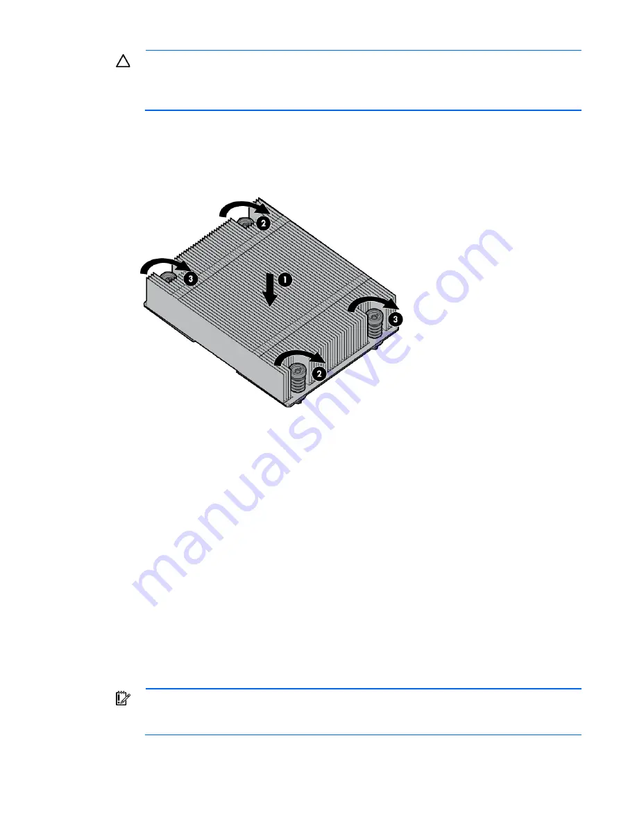
Heatsink retaining screws should be tightened or loosened in diagonally opposite
pairs (in an "X" pattern). Do not overtighten the screws as this can damage the board, connectors,
or screws. Use the wrench supplied with the system to reduce the possibility of overtightening the
screws.
11.
Install the heatsink:
a.
Position the heatsink on the processor backplate.
b.
Tighten one pair of diagonally opposite screws halfway, and then tighten the other pair of screws.
c.
Finish the installation by completely tightening the screws in the same sequence.
12.
Install DIMMs.
13.
Install the processor air baffle.
14.
Install the FlexibleLOM riser cage.
15.
Install the PCI riser cage.
16.
Install the front GPU bracket.
17.
Install the interposer board assembly.
18.
Install the front GPU cage.
19.
Install the hot-plug drive cage.
20.
Install the server into the chassis.
21.
Connect the peripheral cables.
22.
Press the Power On/Standby button.
The server exits standby mode and applies full power to the system. The system power LED changes
from amber to green.
Re-entering the server serial number and product ID
IMPORTANT:
When re-entering the serial number, be sure to use the
server serial number. This
number is located on the front panel serial number/iLO information pull tab. Do not use the
chassis serial number.
Summary of Contents for ProLiant SL250s Gen8
Page 12: ...Customer self repair 12 ...
Page 13: ...Customer self repair 13 ...
Page 14: ...Customer self repair 14 ...
Page 74: ...Cabling 74 SFF hot plug drive cage Front quick release cage Left node ...
Page 75: ...Cabling 75 Right node Rear quick release drive cage Left node ...
Page 78: ...Cabling 78 Mini SAS cabling SFF hot plug drive cage Front quick release drive cage Left node ...
Page 79: ...Cabling 79 Right node Rear quick release drive cage Left node ...
Page 80: ...Cabling 80 Right node FBWC capacitor pack cabling Left node ...
Page 81: ...Cabling 81 Right node ...


