Operations 27
2.
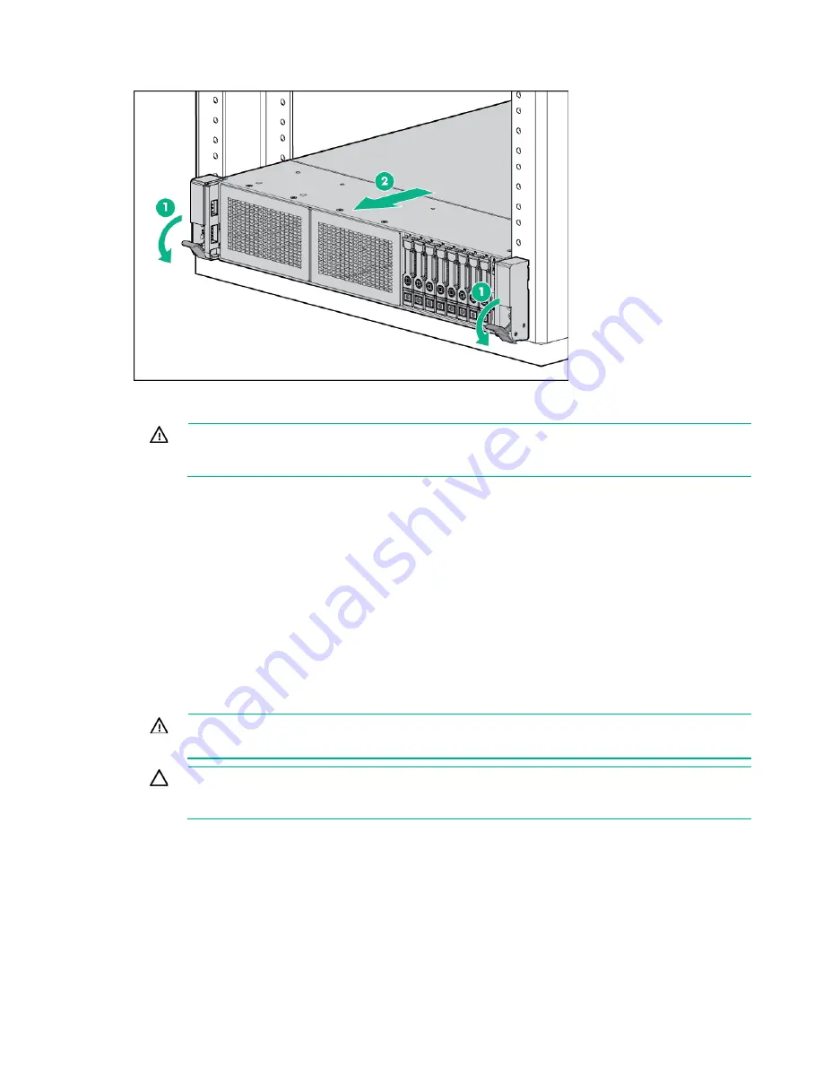
Extend the server from the rack.
3.
After performing the installation or maintenance procedure, slide the server back into the rack, and
then press the server firmly into the rack to secure it in place.
WARNING:
To reduce the risk of personal injury, be careful when pressing the server
rail-release latches and sliding the server into the rack. The sliding rails could pinch your
fingers.
Remove the server from the rack
To remove the server from a Hewlett Packard Enterprise, Compaq-branded, Telco, or third-party rack:
1.
Power down the server (on page
2.
Extend the server from the rack (on page
3.
Disconnect the cabling and remove the server from the rack. For more information, see the
documentation that ships with the rack mounting option.
4.
Place the server on a sturdy, level surface.
Remove the access panel
WARNING:
To reduce the risk of personal injury from hot surfaces, allow the drives and the
internal system components to cool before touching them.
CAUTION:
Do not operate the server for long periods with the access panel open or
removed. Operating the server in this manner results in improper airflow and improper cooling
that can lead to thermal damage.
To remove the component:
1.
Power down the server (on page
2.
Extend the server from the rack (on page
3.
Open or unlock the locking latch, slide the access panel to the rear of the chassis, and remove the
access panel.
Summary of Contents for ProLiant DL380 Gen9
Page 34: ...Operations 34 5 Install the air baffle ...
Page 90: ...Hardware options installation 90 o Connected to a PCI expansion board ...
Page 102: ...Hardware options installation 102 o Connected to a PCI expansion board ...
Page 104: ...Hardware options installation 104 o Secondary riser cage o PCI blank ...
Page 128: ...Hardware options installation 128 o 24SFF drive backplanes Group C SAS cables ...
Page 148: ...Cabling 148 o Connect to a PCI expansion board ...
Page 149: ...Cabling 149 o Connect to an HPE 12G SAS Expander Card Bay 2 installation ...
Page 154: ...Cabling 154 Drive bay 1 is empty Connect using the NVMe power cable 776392 001 ...
Page 171: ...Cabling 171 x4 SATA connector Connect the 2 SFF drive bay power cable ...
Page 173: ...Cabling 173 Secondary PCI riser cage ...
Page 204: ...Support and other resources 204 ...
Page 205: ...Support and other resources 205 ...


