background image

Installing and Configuring the ACL Tape Drive for the 
NonStop NS-Series Server

M8501 and M8502 ACL Tape Drive Installation and User’s Guide — 529972-003

3 -4

Installation

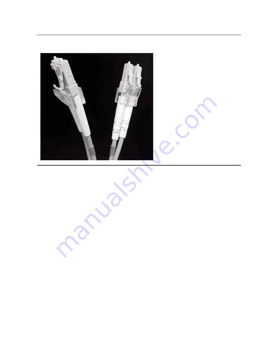
Figure 3-3. LC-LC Fiber Cable

Summary of Contents for M8501

Page 1: ... HP NonStop servers This guide is written for those who install or maintain the M8501 and M8502 ACL tape drives Product Version N A Supported Release Version Updates RVUs This publication supports G06 28 and all subsequent G series RVUs and H06 04 and all subsequent H series RVUs until otherwise indicated by its replacement publication Part Number Published 529972 003 February 2006 ...

Page 2: ...Document History Part Number Product Version Published 529972 001 N A July 2005 529972 002 N A February 2006 529972 003 N A February 2006 ...

Page 3: ...Accessories 1 2 Internal Tape Drive 1 3 Magazine 1 4 Power Supply 1 4 Robotics 1 4 Front Panel Indicators 1 6 2 Setting Up the ACL Tape Drives Setting Up the M8501 ACL Rackmount Unit 2 1 Setting Up the M8502 ACL Tabletop 2 5 3 Installing and Configuring the ACL Tape Drive for the NonStop NS Series Server Overview 3 1 Installation 3 3 Configuration 3 7 4 Operation Front Panel 4 1 Magazine Door 4 2 ...

Page 4: ...ance Introduction 5 1 Running a Cleaning Cartridge 5 1 Automatically Running a Cleaning Cartridge 5 1 Manually Running a Cleaning Cartridge 5 2 Replacing a Cleaning Cartridge in a Reserved Slot 5 3 Replacing a Cleaning Cartridge in the Right Magazine 5 3 6 Troubleshooting Platform Problems 6 1 Error Recovery 6 1 Error Recovery Procedures 6 3 Fault Symptom Codes FSCs 6 3 A Installing and Configurin...

Page 5: ... 2 Figure 4 3 Initialization Screen 4 3 Figure 4 4 ACL Default Screen 4 4 Figure 4 5 Technical Support Information 4 5 Figure 4 6 Access Magazine Screen 4 6 Figure 4 7 Move Media Screen 4 6 Figure 4 8 Move Media Screen Source 4 7 Figure 4 9 Move Media Screen Destination 4 7 Figure 4 10 Power Down Initiation Screen 4 8 Figure 4 11 Menu Screen 4 10 Figure 4 12 View ACL Options Screen Initial Screen ...

Page 6: ...uide 529972 003 iv Table 1 1 Models and Slot Capacities 1 2 Table 3 1 Fiber Cables 3 3 Table 4 1 ACL Front Panel Indicators 4 2 Table 4 2 View ACL Options 4 11 Table 6 1 Error Recovery Procedures 6 3 Table 6 2 Fault Symptom Codes 6 3 Table A 1 Fiber Optic Cables A 4 ...

Page 7: ... and H06 04 and all subsequent H series RVUs until otherwise indicated by its replacement publication Document History New and Changed Information Added information about using the tape drives with HP NonStop S series servers See Section A Installing and Configuring the ACL Tape Drive for the NonStop S Series Server Updated information for configuring the tape drive to NonStop servers See Section ...

Page 8: ...What s New in This Manual M8501 and M8502 ACL Tape Drive Installation and User s Guide 529972 003 vi New and Changed Information ...

Page 9: ...ample MAXATTACH lowercase italic letters Lowercase italic letters indicate variable items that you supply Items not enclosed in brackets are required For example file name computer type Computer type letters within text indicate C and Open System Services OSS keywords and reserved words Type these items exactly as shown Items not enclosed in brackets are required For example myfile c italic comput...

Page 10: ...owing a pair of brackets or braces indicates that you can repeat the enclosed sequence of syntax items any number of times For example M address new value 0 1 2 3 4 5 6 7 8 9 An ellipsis immediately following a single syntax item indicates that you can repeat that syntax item any number of times For example s char Punctuation Parentheses commas semicolons and other symbols not previously described...

Page 11: ...led procedure and returns data to the calling program For example error COMPRESSEDIT filenum i o i i In procedure calls the i i notation follows an input string parameter that has a corresponding parameter specifying the length of the string in bytes For example error FILENAME_COMPARE_ filename1 length i i filename2 length i i o i In procedure calls the o i notation follows an output buffer parame...

Page 12: ...ces is a list of all possible items that can be displayed of which one is actually displayed The items in the list can be arranged either vertically with aligned braces on each side of the list or horizontally enclosed in a pair of braces and separated by vertical lines For example obj type obj name state changed to state caused by Object Operator Service process name State changed from old objsta...

Page 13: ...e o notation following a token or field name indicates that the token or field is optional For example ZSPI TKN MANAGER token type ZSPI TYP FNAME32 o Change Bar Notation Change bars are used to indicate substantive differences between this manual and its preceding version Change bars are vertical rules placed in the right margin of changed portions of text figures tables examples and so on Change ...

Page 14: ...About This Manual M8501 and M8502 ACL Tape Drive Installation and User s Guide 529972 003 xii Change Bar Notation ...

Page 15: ... M8502 comes in a tabletop configuration These auto cartridge loader tape drives connect to the Fibre Channel ServerNet adapter FCSA on the NonStop NS series server by a fiber optic cable Figure 1 1 shows how the ACL tape drives connect to the NonStop NS series server For information about the NonStop S series server see Section A Installing and Configuring the ACL Tape Drive for the NonStop S Ser...

Page 16: ...es These auto cartridge loader tape drives are configured with one internal LTO Gen 3 tape drive along with one removable tape cartridge magazine Figure 1 1 Hardware Configuration Table 1 1 Models and Slot Capacities Model Drives Slots LTO M8501 1 15 LTO 12 0 TB M8502 1 15 LTO 12 0 TB ACL Tape Fiber Cable FCSA NonStop NS Series Server Drive ...

Page 17: ...CL Tape Drive Installation and User s Guide 529972 003 1 3 Internal Tape Drive Internal Tape Drive The ACL units supports a single internal tape drive The internal tape drive can be hot swapped Figure 1 2 Rear View of Tape Drive Single Drive ...

Page 18: ... GUI touch screen however a manual power disconnect switch located at the rear of the power supply may also be used Robotics The ACL tape drive s robotics consist of a cartridge shuttle motor hardware motor drives and other support electronics These robotics are capable of picking and placing tapes throughout the tape drive and the tape cartridge magazine The cartridge shuttle assembly includes a ...

Page 19: ...Overview and Features M8501 and M8502 ACL Tape Drive Installation and User s Guide 529972 003 1 5 Robotics Figure 1 4 View of Barcode Reader and Shuttle Assembly Barcode Reader Shuttle ...

Page 20: ...s The ACL tape drive s front panel indicators consist of Viewing window lets you visually check the unit s internal operations GUI touch screen manually operated to setup and configure the unit ACL module status LED displays the unit s operational status Figure 1 5 Front Panel Indicators ACL Status LED GUI Touch Screen Internal Viewing Window ...

Page 21: ...torage cabinet slide rails to install the unit in a standard 19 inch rack storage cabinet To set up the rackmount model 1 Ensure that you have adequate space available in the rack 2 Use the template that is shipped with the unit to mark the location of the mounting hardware on the mounting rails of the storage cabinet Setting Up the M8501 ACL Rackmount Unit 2 1 Setting Up the M8502 ACL Tabletop 2 ...

Page 22: ...elow the planned position of the new unit then place the template against the front of the mounting rack and rest it on top of the previously installed unit c Use the front of the template to mark the attachment points for mounting brackets rails components or cage nuts on the back of the storage cabinet d Use the back of the template to mark the attachment points for the mounting brackets rails c...

Page 23: ...29972 003 2 3 Setting Up the M8501 ACL Rackmount Unit 6 Attach the slide members using the supplied fasteners Install the clip nuts on the inside of the slide member s front and back mounting bracket only if the vertical rail mounting holes are not tapped Figure 2 2 Installing the Slide Members ...

Page 24: ... the bearing carrier is in the retained position 10 Lift the unit and visually align the inner and middle slide members 11 Verify the ball bearing slide members are located in the front position 12 Slide the unit completely into the rack until the front panel touches the rack 13 Remove and discard the tape that holds the door in the latched position leaving the door open Figure 2 3 Installing Slid...

Page 25: ...Setting Up the M8502 ACL Tabletop The M8502 ACL tabletop requires no mechanical assembly for mounting See Figure 2 4 Place the unit on a desk table or other stable horizontal surface Ensure that the cooling grills at the front and the fans at the rear of the unit are not obstructed Allow 12 inches 30 4 centimeters of clearance at the front and 6 inches 15 2 centimeters at the rear of the unit to a...

Page 26: ...Setting Up the ACL Tape Drives M8501 and M8502 ACL Tape Drive Installation and User s Guide 529972 003 2 6 Setting Up the M8502 ACL Tabletop ...

Page 27: ...he NonStop NS Series Server This section includes Overview A multimode shortwave fiber optic cable must be used to connect the ACL tape drive to the Fibre Channel ServerNet adapter FCSA on the HP NonStop NS series server Figure 3 1 shows how the ACL tape drive connects to the server Overview 3 1 Installation 3 3 Configuration 3 7 ...

Page 28: ...ng the ACL Tape Drive for the NonStop NS Series Server M8501 and M8502 ACL Tape Drive Installation and User s Guide 529972 003 3 2 Overview Figure 3 1 Hardware Configuration Tape Drive Fiber Cable FCSA NonStop NS Series Server ...

Page 29: ...nect the other end of the fiber cable to the Fibre Channel ServerNet adapter FCSA on the NonStop NS series server See Figure 3 4 on page 3 5 for the location An LC LC fiber optic cable must be used to connect the ACL tape drive to the FCSA Figure 3 3 on page 3 4 shows each side of the cable Figure 3 2 Tape Drive s Fibre Channel Port Connection Table 3 1 Fiber Cables Connector Fiber Cable Fiber Cab...

Page 30: ...Installing and Configuring the ACL Tape Drive for the NonStop NS Series Server M8501 and M8502 ACL Tape Drive Installation and User s Guide 529972 003 3 4 Installation Figure 3 3 LC LC Fiber Cable ...

Page 31: ...r end into an AC power outlet 4 Toggle the power switch to the on position from the rear of the unit 5 Press anywhere on the GUI touch screen to activate the display and then turn the unit on Figure 3 4 View of Two FCSAs at the Rear of the Server Note The tape drive does not have protection against lightning surges Customers in high risk areas should use external surge protection rated for use in ...

Page 32: ...g the ACL Tape Drive for the NonStop NS Series Server M8501 and M8502 ACL Tape Drive Installation and User s Guide 529972 003 3 6 Installation Figure 3 5 Powering On the ACL Tape Drive GUI Touch Screen Power Cord Toggle Switch ...

Page 33: ... s Guide 529972 003 3 7 Configuration Configuration Follow Steps 1 through 4 to navigate through the ACL tape drive s menu configuration to view the PORTNAME of the tape drive The PORTNAME is added to the SCF configuration in Step 5 on page 3 8 1 Press the Status button on the GUI touch screen Figure 3 6 Status Button Status Button ...

Page 34: ...APE tape SENDTO STORAGE LOCATION group module slot SAC sac id PORTNAME 64 bit portname LUN lun id Example SCF ADD TAPE TAPE1 SENDTO STORAGE LOCATION 110 2 3 SAC 1 PORTNAME 50060B00002E0934 LUN 0 6 To start the ACL tape drive on the server issue this command in SCF SCF START TAPE tape Example SCF START TAPE TAPE1 For complete details about the ADD and START commands including command syntax see the...

Page 35: ...he ACL units include the left magazine door a graphical user interface GUI touch screen an ACL status LED and a viewing window See Figure 4 1 Front Panel 4 1 Display Screens and Options 4 4 Menu Selections 4 10 Inserting and Removing Tape Cartridges 4 13 Figure 4 1 Front Panel Left Magazine Viewing Door Window GUI Touch Screen ACL Status LED ...

Page 36: ...hanical release at the center of the door Indicators The ACL tape drive s front panel indicators consist of a GUI touch screen and an ACL status LED Figure 4 2 Magazine Door Mechanical Release Table 4 1 ACL Front Panel Indicators Indicator Description Solid Green The ACL is operating correctly under normal conditions Flashing Green The ACL is operating correctly however a change is being made via ...

Page 37: ...tion Screen Initialization Screen When power is first applied to the ACL tape drives a series of power on self test POST diagnostics are performed After the POST completes this initialization screen appears Figure 4 3 Initialization Screen Note Pressing Continue will display the ACL default screen ...

Page 38: ...pears as shown in Figure 4 4 The ACL Default screen enables you to select these options Technical Support Information HP logo Magazine Access Move Media LCD Contrast Controls Power Status Online Menu Display Screens and Options The ACL GUI touch screen displays graphics and text in the form of easy to understand messages Graphics and text messages along with their functions are described in this s...

Page 39: ...t Information Option Technical Support Information Option Selecting the HP logo in the top left corner displays technical support information specific to HP See Figure 4 5 Figure 4 5 Technical Support Information Note The HP Global Customer Support Center GCSC provides technical support for this product ...

Page 40: ... 4 6 The Access Magazine option lets you gain access to the left magazine door for tape cartridge placement or removal Move Media Selecting this option lets you display the Move Media screen See Figure 4 7 The Move Media option lets you remove a cartridge from the tape drive load a cartridge to the tape drive or to move cartridges within the ACL Figure 4 6 Access Magazine Screen Figure 4 7 Move Me...

Page 41: ...pe from the Move Media Screen The Source input box will change from gray to an active state See Figure 4 8 2 Touch the source you want to move from the Source Element Type selections The options available are Drive and Slot 3 Touch the Destination Input Box on the Move Media Screen The Destination Input Box changes from gray to an active state See Figure 4 9 Figure 4 8 Move Media Screen Source Fig...

Page 42: ...n the Destination Input Box 5 Press the Execute Move button The ACL robotics move the cartridge from the Drive to Slot 3 LCD Contrast Controls Selecting these options let you increase or decrease the contrast of the LCD display Incremental steps are set by adjusting the LCD contrast controls up and down arrows from the upper right corner of the ACL Default Screen Incremental steps can range from 0...

Page 43: ...n You can identify a tape drive type view physical tape drive status tape drive cleaning information and tape cartridge information by opening the corresponding areas on the screen Online Selecting this option from the ACL Default Screen lets you place the ACL online or offline Note By default the ACL automatically comes online after a power up initialization ...

Page 44: ...displays three distinct areas View System Data Utilities Edit Options View System Data The View System Data area lets you select these screens ACL Options SCSI Options Network Options ACL Info Cartridge Map ACL Options Selecting this option lets you view but not modify the ACL settings as defined in the ACL option of the Edit Options area Table 4 2 on page 4 11 describe the available options Figur...

Page 45: ...I touch screen The default is Disabled Auto Power up on Installed Drive Enables a tape drive to be automatically powered up after a delay after replacing a tape drive Unload Mode Selects the unload mode for ACL tape drives If Implicit the ACL unloads a tape drive before attempting to move a cartridge from that tape drive If Explicit the server must issue a SCSI UNLOAD command to a tape drive befor...

Page 46: ...rence Barcode Label Size Lets you limit the maximum number of characters of the barcode label Possible settings are 1 through 8 The default is 8 Barcode Label Alignment Lets you specify the alignment of a barcode label The options are Left to Right When used in conjunction with the label size option this option strips unwanted trailing characters left alignment or leading characters right alignmen...

Page 47: ...ther through your host system software or by using the Move Media option on the Default Screen Removing the Magazine You must manually remove the ACL magazine To access the magazine use the Magazine Access option on the Default Screen This option lets you open the left magazine door After opening the magazine door pull the magazine out and away from the ACL chassis Inserting Cartridges into the Ma...

Page 48: ...ife 1 Place labels only in the recessed area just above the write protection switch See Figure Never place labels on the top bottom sides or rear of the cartridge they can cause loader faults and interfere with normal operations Such labels can come off inside the equipment causing damage 2 Always inspect cartridges for incorrect or improperly attached labels 3 Never erase information on a cartrid...

Page 49: ...2 ACL Tape Drive Installation and User s Guide 529972 003 4 15 Barcode Labels Note Barcode labels may be placed on the media with the alphanumeric characters on the left or the right Figure 4 14 Barcode Label Installation LTO ...

Page 50: ...Operation M8501 and M8502 ACL Tape Drive Installation and User s Guide 529972 003 4 16 Barcode Labels ...

Page 51: ...the Clean One Drive menu option from the Maintenance submenu on the front panel display Automatically Running a Cleaning Cartridge You can configure the ACL tape drive so that it automatically runs the cleaning cartridge mode After a tape drive that needs cleaning completes an unload operation it sends a cleaning needed message to the unit This activates an automatic cleaning cycle if the cleaning...

Page 52: ...t expires and needs to be replaced Running a Cleaning Cartridge from a Data Cartridge Slot 1 Install a cleaning cartridge into an appropriate data cartridge slot Slot 0 for example 2 Select the Clean One Drive menu option from the Maintenance submenu on the front panel display 3 Select Source If the default entry is not the slot with the cleaning cartridge press Slot in the Element Type box to seq...

Page 53: ... When the destination entry is correct select Execute Clean 6 When the cleaning cycle completes the unit returns the cleaning cartridge back to the cleaning cartridge slot To remove the cleaning cartridge select Magazine Access from the unit s Status screen Replacing a Cleaning Cartridge in a Reserved Slot When the cleaning cartridge has been used up a message appears on the front panel display in...

Page 54: ...Maintenance M8501 and M8502 ACL Tape Drive Installation and User s Guide 529972 003 5 4 Replacing a Cleaning Cartridge in the Right Magazine ...

Page 55: ...formation on how to correctly install and configure the unit General drive errors usually result from a miscommunication between the ACL and tape drive or a mechanical malfunction within the ACL Both platform problems and general drive errors display an error message and a Fault Symptom Code FSC on the GUI touch screen Use an FSC to report errors to your service provider or in some cases to determ...

Page 56: ...Troubleshooting M8501 and M8502 ACL Tape Drive Installation and User s Guide 529972 003 6 2 Error Recovery Figure 6 1 Troubleshooting Flow Chart ...

Page 57: ... to the ACL and inspect connectors and cables F Invalid operation Select parameters correctly and try again G Call Technical Support Table 6 2 Fault Symptom Codes Message FSC ERP Novram Update Error 0306 G The nonvolatile configuration area in flash memory could not be updated programming error Barcode Not Active Error 0501 D G Catastrophic Smx operating system error task creation error unexpected...

Page 58: ... force opened or door sensor failed Cart Inaccessible 200C F For an LTO indicates the tape is not ejected Cartridge in drive is not accessible from changer Drive In Error 200D C G A general drive error detected by control task No Magazine 200E F Cannot move element not installed from changer Removal Prevented 200F F Receive medium prevent removal from drive for a fetch Ctl Firmware Error 2010 C G ...

Page 59: ... motors has been disabled and could not be re enabled Picker Tach Errors 3002 C G Picker Tach errors were detected when checking slots Bin Fetch Failure 3001 C G Loader failed to fetch a cartridge from a bin Drive Fetch Failure 3013 C G Loader failed to fetch a cartridge from the drive Drive Time out Failure 3015 C D G Loader detects unload command time out Drive Status Failure 3016 C D G Detected...

Page 60: ...etected an unexpected status and could not recover internal target error Loader Received Invalid Command 3041 C G The loader task received an unexpected command and could not recover internal target error Motor Firmware Error 3042 C G The loader task detected an unexpected status and could not recover internal target error Missing Magazine 3050 F In diag no magazine installed for diag to run No Ca...

Page 61: ...ive detected an SDLT cartridge and the cartridge has been returned to its orign Drive Stow Failed Media Remains in Drive 3083 F The DLT drive detected an SDLT cartridge but the cartridge could not be returned to its origin UnSupported Drive For Requested Operation 3084 F Unsupported drive type No Retry On Fetch Stow 308F F The loader retried an operation and retries were disabled Picker Jammed 310...

Page 62: ...pass thru shuttle could not reach the target location Vertical Elevator Jammed 3500 C G The vertical elevator could not reach the target location All Slots Empty 5011 F There are no cartridges installed in any of the reserved cleaning slots DLT Already Loaded 5014 F The cleaning operation failed because the drive already has a cartridge inserted Expired Clean g Cart 5015 F The cleaning operation f...

Page 63: ...message was invalid 7007 C D G An Updated Drive Status message was received from a module but the drive index was out of range The Drive response was not expected 7008 C D G A command response was received from a Drive task to which a command had not been sent The opcode for a WORD message was unknown 7009 C D G A WORD sized message was received but the message opcode could not be identified The o...

Page 64: ... is indicating that a command has failed to complete successfully Sequential command execution failed 7016 C G The Sequential task is indicating that a command has failed to complete successfully Destination Xchg for msg was Null 7017 C G Attempting to send a message to a task but the argument exchange pointer was Null Bad src mod in peg msg 7018 C G A message was received from a remote module but...

Page 65: ...ompleting a SCSIInitcommand the current state of the save operation was unknown Cartridge reject recovery failed 8001 C D G The DLT drive failed to successfully load a tape even after retries Drive Fan stalled 8002 C D G The fan in the drive hot swap shoe is either not installed or has stalled Drive load did not complete 8003 C D G The drive failed to successfully load a tape Invalid drive was ins...

Page 66: ... NULL comm A007 C G An attempt to place a Comm block on a task s exchange failed the argument Comm block pointer was NULL Msg contains no comm A008 C G A message obtained from the free pool did not contain a Comm block Comm return address in unknown A009 C G An attempt to return a command response to the originating task failed because the originator could not be determined Bad Image CRC F001 F Th...

Page 67: ...allation and User s Guide 529972 003 6 13 Fault Symptom Codes FSCs If an error message appears that is not included in Table 6 2 write down the fault code number and follow the recovery procedure If the same error occurs again call your service provider ...

Page 68: ...Troubleshooting M8501 and M8502 ACL Tape Drive Installation and User s Guide 529972 003 6 14 Fault Symptom Codes FSCs ...

Page 69: ... via an IOAM enclosure The tape drive attaches to the FCSA Fibre Channel ServerNet adapter in the IOAM enclosure The ServerNet switch board in the IOAM enclosure connects to a MSEB modular ServerNet expansion board on a NonStop S series server via a fiber optic cable Figure A 1 on page A 2 shows a configuration example of the tape drive connected to a NonStop S series server via an IOAM enclosure ...

Page 70: ...9972 003 A 2 Configuration Overview For more information on the IOAM enclosure see the Modular I O Installation and Configuration Guide Figure A 1 Configuration Example NonStop Modular Rack Tape Drive S Series Rear View System IOAM Enclosure MSEBs ServerNet Switch Board Fibre Channel Fiber optic Cable Adapter FCSA ServerNet Fiber optic Cable ...

Page 71: ...ive Installation and User s Guide 529972 003 A 3 Installation Installation 1 Unpack and check the shipment 2 Choose a site for the tape drive 3 Place the tape drive on a flat sturdy and level surface The device must be in an environment that is free of dust and humidity Figure A 2 Front View of Tape Drive ...

Page 72: ...cable must be used to connect the tape drive to the FCSA on the IOAM enclosure The fiber optic cable is a multimode short wave fiber optic cable This cable is normally an orange color Table A 1 Fiber Optic Cables Connector Fiber Optic Cable Fiber Cable Distance LC LC 50 125 µm 2 300 meters 6 56 984 25 feet LC LC 62 5 125 µm 3 150 meters 9 84 492 13 feet Figure A 3 LC LC Fiber Optic Cable ...

Page 73: ...501 and M8502 ACL Tape Drive Installation and User s Guide 529972 003 A 5 Installation 4 Connect one end of the fiber optic cable to the top Fibre Channel port at the rear of the tape drive See Figure A 4 for the location Figure A 4 Rear Components of Tape Drive Fibre Channel Port ...

Page 74: ...tallation and User s Guide 529972 003 A 6 Installation 5 Connect the other end of the fiber optic cable to a Fibre Channel port on a Fibre Channel ServerNet adapter FCSA at the rear of the IOAM enclosure See Figure A 5 for the location of the ports Figure A 5 View of Two FCSAs at Rear of Server Fiber Optic Cables ...

Page 75: ...nstallation and User s Guide 529972 003 A 7 Installation An LC SC cable is used to connect the IOAM enclosure to the NonStop S series server 6 Connect the LC side of the fiber optic cable to a port on the ServerNet switch board at the rear of the IOAM enclosure Figure A 6 LC SC Fiber Optic Cable SC Side LC Side ...

Page 76: ...ing the ACL Tape Drive for the NonStop S Series Server M8501 and M8502 ACL Tape Drive Installation and User s Guide 529972 003 A 8 Installation Figure A 7 Rear View of IOAM Enclosure ServerNet Switch Board Fibre Channel Ports ...

Page 77: ...Series Server M8501 and M8502 ACL Tape Drive Installation and User s Guide 529972 003 A 9 Installation 7 Connect the SC side of the fiber optic cable to a fiber optic PIC on the MSEB at the rear of the server Figure A 8 View of MSEB at Rear of Server Fiber optic PIC ...

Page 78: ... See Figure 3 5 on page 3 6 for the location Then plug the other end into an AC power outlet 9 Toggle the power switch to the on position from the rear of the unit See Figure 3 5 on page 3 6 for the location Note The tape drive does not have protection against lightning surges Customers in high risk areas should use external surge protection rated for use in their location and be able to handle th...

Page 79: ... User s Guide 529972 003 A 11 Configuration Configuration Follow Steps 1 through 4 to navigate through the ACL tape drive s menu configuration to view the PORTNAME of the tape drive The PORTNAME is added to the SCF configuration in Step 5 on page A 12 1 Press the Status button on the GUI touch screen Figure A 9 Status Button ...

Page 80: ...D TAPE tape SENDTO STORAGE LOCATION group module slot SAC sac id PORTNAME 64 bit portname LUN lun id Example SCF ADD TAPE TAPE1 SENDTO STORAGE LOCATION 110 2 3 SAC 1 PORTNAME 50060B00002E0934 LUN 0 6 To start the ACL tape drive on the server issue this command in SCF SCF START TAPE tape Example SCF START TAPE TAPE1 For complete details about the ADD and START commands including command syntax see ...

Page 81: ...when the equipment is operated in a commercial environment This equipment generates uses and can radiate radio frequency energy and if not installed and used in accordance with the instruction manual may cause interference to radio communications Operation of this equipment in a residential area is likely to cause harmful interference in which case the user will be required to correct the interfer...

Page 82: ...a MIC Compliance Taiwan BSMI Compliance Japan VCCI Compliance This is a Class A product based on the standard or the Voluntary Control Council for Interference by Information Technology Equipment VCCI If this equipment is used in a domestic environment radio disturbance may occur in which case the user may be required to take corrective actions ...

Page 83: ...tic transceiver Each of these devices contains a laser that is classified as a Class 1 Laser Product in accordance with US FDA regulations and the IEC 60825 1 The product does not emit hazardous laser radiation The Center for Devices and Radiological Health CDRH of the U S Food and Drug Administration implemented regulations for laser products on August 2 1976 These regulations apply to laser prod...

Page 84: ...N DIENEN NUR DEM INTERNEN GEBRAUCH DUAL POWER CORDS CAUTION THIS UNIT HAS MORE THAN ONE POWER SUPPLY CORD DISCONNECT ALL POWER SUPPLY CORDS TO COMPLETELY REMOVE POWER FROM THIS UNIT ATTENTION CET APPAREIL COMPORTE PLUS D UN CORDON D ALIMENTATION DÉBRANCHER TOUS LES CORDONS D ALIMENTATION AFIN DE COUPER COMPLÈTEMENT L ALIMENTATION DE CET ÉQUIPEMENT DIESES GERÄT HAT MEHR ALS EIN NETZKABEL VOR DER WA...

Page 85: ...ERSTELLEN COURANT DE FUITE E LEVE RACCORDEMENT A LA TERRE INDISPENSABLE AVANT LE RACCORDEMENT AU RESEAU FUSE REPLACEMENT CAUTION For continued protection against risk of fire replace fuses only with fuses of the same type and the same rating Disconnect power before changing fuses Waste Electrical and Electronic Equipment WEEE Information about the Waste Electrical and Electronic Equipment WEEE dir...

Page 86: ...Safety and Compliance M8501 and M8502 ACL Tape Drive Installation and User s Guide 529972 003 Statements 6 Important Safety Information ...

Page 87: ...4 2 access magazine option 4 6 default screen 4 4 initialization screen 4 3 menu selections 4 10 move media 4 6 viewing window 1 6 L LTO Ultrium gen 3 tape drive 1 1 M Magazine door 4 2 Maintenance 5 1 N NonStop NS series server configuration 3 7 installation 3 3 P POST 4 3 Power supply 1 4 R Robotics 1 4 S Shuttle assembly 1 5 Supported connections 3 3 T Tape cartridge magazine 1 2 1 4 4 14 Tape ...

Page 88: ...Index M8501 and M8502 ACL Tape Drive Installation and User s Guide 529972 003 Index 2 T ...

Reviews: